

Учебное пособие 1988
.pdfIssue № 1 (49), 2021 |
ISSN 2542-0526 |
manufactured from high-strength concrete and steels. One of the ways that makes it possible to significantly contribute to the solution of these important problems is extensive use of thinwalled closed-profile elements made of high-strength centrifuged concrete. The key advantage of centrifuged products and structures is based on using a highly mechanized method of compacting the concrete mixture where some of the excess water is taken away during the formation process, the water-cement ratio drops while the strength and density of concrete increases. The use of centrifuged reinforced concrete helps to reduce the material consumption of the main supporting structures of buildings and structures as well as to improve the quality and reliability of products.
An underrated production technology, centrifugation characterizes only concretes and concrete structures of varying cross-section, i.e. those that differ in their characteristics (density, strength, deformability, etc.). In many cases, this must be considered in the calculation and design, but such investigations have almost not been conducted. In this regard, while calculating and designing building structures of a variatropic structure, an unreasonably large margin is usually laid causing a considerable rise in the cost of promising building
Unlike the normative one, the diagrammatic approach to the calculation, does not make use of individual strength and deformation characteristics of materials, but their full stress-strain diagrams with descending branches. At the same time, if the normative approach is crucial to the load-bearing capacity, deformability and crack resistance of structures discretely –– based on completely different prerequisites at different stages of operation of the elements, the diagrammatic approach is crucial to the load-bearing capacity, deformability and crack resistance integrally –– based on iterative calculation carried out from the start of operation of the exhaustion of the load-bearing abilities according to the same premises.
Strictly speaking, the division of approaches into normative and diagrammatic is currently a rather arbitrary one as the diagrammatic approach is also sometimes recommended by the norms. However, according to the established practice, they are nevertheless separated for the sake of navigation.
Compressed reinforced concrete elements are commonly made using three major technologies –– vibration, centrifugation and vibration centrifugation. However, all the main calculated dependencies for identifying their load-bearing capacity are derived from the main postulate, i.e., the constancy and equality of the characteristics of concrete over the section, which actually applies only to vibrated columns [1––6, 9, 10, 12].
Therefore it appears essential to check the diagrammatic approach in a variety of settings for columns of all these types and to improve their calculation considering all of the above.
31

Russian Journal of Building Construction and Architecture
1. Calculating the strength of short centrally compressed reinforced concrete columns.
Iterative design equations are the following: –– for concrete elements:
h |
|
(1) |
N Nb 0 |
σ(ε)Abdx , |
|
where Nb is the load-bearing capacity of concrete; σ(ε) is the compressive stress in concrete depending on the relative deformation; Ab is the area of compressed concrete; dx is the height of the compressed zone; h is the section height;
–– for reinforced-concrete elements:
h |
|
(2) |
N Nb Ns 0 |
σ(ε)Abdx σsc As , |
|
where Ns is the load-bearing capacity of the reinforcement; σsc is the design compressive strength of reinforcement; As is the cross-sectional area of the reinforcement.
Calculation according to standard or integral characteristics of concrete (common for the entire section) makes use of deformation diagrams “σb – εb”.
Direct integration of equations (1) and (2) is replaced by finite summation in the sections: –– for concrete elements:
h |
|
(3) |
N Nb 0 |
σ(ε)Abdx; |
|
–– for reinforced concrete elements:
h |
(4) |
|
N Nb Ns 0 σ(ε)Abdx σsc As . |
||
|
The calculation according to the differential characteristics of concrete (differing in crosssection for centrifuged and vibrocentrifuged columns) will be based on other equations:
–– for concrete elements:
h |
ω2 |
D |
σ(ε)Abidxdωdl; |
(5) |
Nb 0 |
ω |
d |
|
|
|
1 |
|
|
|
where ω1 is the internal angular velocity of rotation; ω2 is the external angular velocity of rotation; d is the inner diameter of the column; D is the outer diameter of the column; Abi is the area of the compressed concrete layer; dω is the angular speed of rotation; dl is the distance from the center of rotation to the center of the grain;
–– for reinforced concrete elements:
h |
ω2 |
D |
σ(ε)Abidxdωdl σsc As. |
(6) |
N Nb Ns 0 |
ω |
d |
|
|
|
1 |
|
|
|
In the iterative approach, the calculation for each iteration is performed according to the concrete deformations εb specified with a certain step. Equations of projections for concrete or
32

Issue № 1 (49), 2021 |
ISSN 2542-0526 |
reinforced concrete elements are compiled for calculation according to the normative, integral or differential characteristics of concrete.
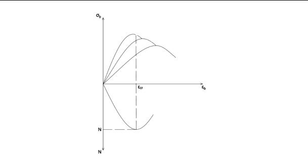
What is special about the iterative calculation is that it makes it possible to assess the loadbearing capacity of compressed elements not only in the critical, but also in the supercritical stage using calculation considering the frequent situation where the decrease in stresses in concrete on the descending branch of the diagram is compensated for and even overlaps with an increase in stresses in the reinforcement (Fig. 1):
Ns Nb . |
(7) |
where ∆Ns is an increase in the effort in the reinforcement; ∆Nb is a reduction in the effort in the reinforcement.
Fig. 1. Compensation for reduced force in concrete increase in force in reinforcement with a diagrammatic approach
Note that this must certainly be a high-strength reinforcement with a diagram without a yield plate. In the case of conventional reinforcement with a diagram, with a yield point, the loadbearing capacity of the element will be exhausted when the maximum concrete strength has been reached.
The initial data for the iterative calculation are: analytical deformation diagrams “stress σ –– deformation ε” of concrete and high-strength reinforcement; shape and dimensions of the crosssection of the element; areas of concrete and reinforcement.
33

Russian Journal of Building Construction and Architecture
As a design prerequisite, the condition of compatibility of deformations of concrete and reinforcement at all stages of work, including supercritical one, is taken:
εb εs ε. |
(8) |
where εb is the concrete deformation; εs is the reinforcement deformation.
The longitudinal force perceived by the section at all stages of operation is calculated as:
N Nb Ns σb (εb )Ab σs (εs )As ; |
(9) |
where σb are stresses in the concrete; σs are stresses in the reinforcement; or considering (8):
N Nb Ns σb (ε)Ab σs (ε)As . |
(10) |
The load-bearing capacity identified by the maximum longitudinal force perceived by the section will be characterized by the maximum of the function “longitudinal force N –– longitudinal deformation ε”, i.e.:
dN |
(11) |
|
dε 0. |
||
|
According to (11), it is possible to identify the deformations of concrete and reinforcement ε = εb = εs, from which, after substituting ε in (10), the maximum longitudinal force N, i.e. load-bearing capacity, can be identified.
Analytical diagrams of deformation of concrete and reinforcement “σ – ε” were taken in the form of the EKB-FIP formula with the substitution of our recommendations for identifying the strength and deformation characteristics of concrete [7, 8, 11, 18] and high-strength reinforcement [13, 14, 19––21].
The calculation was performed in the following way.
A certain value of concrete deformation εb = ε was set in the region close to the maximum of the diagram “σb – εb”, respectively, the deformations of the reinforcement were also taken equal to εs = ε.
The stresses in concrete and reinforcement were calculated from their analytical diagrams “σ – ε”.
The forces Nb and Ns, taken by concrete and reinforcement, and the total load-bearing capacity of the section N = Nb + Ns were identified.
Then, a new value of concrete deformation εb = ε + ∆ε was set, and the described calculation was repeated. In this way, several iterations were performed until the value of N reached its maximum and started to drop.
The maximum value of N corresponded to the load-bearing capacity of the reinforced concrete column.
34
Issue № 1 (49), 2021 |
ISSN 2542-0526 |
Additional explanations should be then made related to the value of the longitudinal deformations of concrete εcr where the maximum value of N was reached, i.e., the load-bearing capacity was exhausted.
In vibrated reinforced concrete columns where layers of concrete had the same strength and deformability characteristics, the longitudinal deformations of concrete εcr when the loadbearing capacity of the columns is generally exhausted could be equal to or greater than the ultimate deformations of concrete εbR corresponding to the maximum concrete strength Rb, in connection with which and the stresses in the concrete of the entire section at the exhaustion of the load-bearing capacity of the columns could be equal to or less than Rb.
In the first case (<), this occurred with weak reinforcement of the columns, the increase in the forces in the reinforcement of which could not compensate for the reduction in the force in concrete after reaching the maximum of its deformation diagram Rb; εbR.
In the second case (=), this occurred with strong or re-reinforcement of the columns, the increase in forces in the reinforcement of which not only compensated, but also overlapped the reduction in the force in concrete after reaching the maximum of its deformation diagram Rb; εbR, which generally increased the load-bearing capacity of the columns and exhausted it when the concrete was already deformed on the descending branch of its diagram.
In centrifuged and vibrocentrifuged reinforced concrete columns where all the layers of concrete had unequal characteristics of strength and deformability, the longitudinal deformations of concrete εcr when the load-bearing capacity of the columns is generally exhausted for all the layers are also the same, but they could be less, equal or greater than the ultimate deformations of concreteεbRi ofaconcretelayercorrespondingtothemaximumstrengthoftheirconcreteRbi.
This time around it is connected not only with the degree of reinforcement of the columns, but also with the difference in the strength and deformation characteristics of the concrete layers, each of which when the load-bearing capacity of the column is exhausted can deform both on the ascending and descending branches of its deformation diagram.
Hence a situation is quite possible when the depletion of the load-bearing capacity of the column at the same deformations εcr for all the layers of its concrete occurs when the inner layer is still in the ascending layer, the middle layer is at the maximum, and the outer layer is already on the descending branch of its deformation diagrams “σb – εb” (Fig. 2).
Therefore the design equations with a single term for concrete of vibrated columns are transformed into equations with three (according to the number of conditional layers) terms for concrete of centrifuged and vibrocentrifuged columns.
35
Russian Journal of Building Construction and Architecture
Upper layer
Middle layer
Internal layer
Fig. 2. Deformations and stresses in conditional concrete layers when the loadbearing capacity of a column of variatropic section is exhausted
Accordingly, the picture of the distribution of forces in concrete layers and in reinforcement when the load-bearing capacity of the columns is exhausted becomes a lot more complicated [15––17]. Now it is possible here that even with a weak reinforcement of the columns, the reduction in the force in the concrete of the inner layer after reaching the maximum of its deformation diagram can be compensated not by the increase in the force in the reinforcement, but by that in the force in the outer layer or even immediately in the outer and middle layers, particularly for vibrocentrifuged columns.
Hence variatropic sections of building structures have a significantly greater ability to redistribute stresses and forces than conventional ones.
An analysis of the results of a physical and numerical experiment, which will be further described, made it possible to establish that the depletion of the load-bearing capacity of compressed reinforced concrete columns occurs at deformations εcr which are in the range 0.85 ... 1.15εbR.
Hence in order to reduce the number of calculated iterations and the possibility of conducting them manually, the suggested calculation can be implemented, in addition to an iterativeone, also by means of approximate and simplified methods.
2. An approximate calculation of the load-bearing capacity of centrifuged and vibrocentrifuged reinforced concrete columns. In order to calculate the load-bearing capacity of centrifuged and vibrocentrifuged reinforced concrete columns, it is suggested that the calculation in just three iterations is proposed. In this case, the deformations εcr for each iteration can
36
Issue № 1 (49), 2021 |
ISSN 2542-0526 |
be taken equal to 0.9; 1; 1.1εbR, assuming the value of εbR in centrifuged and vibrocentrifuged columns equal to εbR of the middle layer.
Additionally, considering the high-strength reinforcement A600 operating in the column when its load-bearing capacity is almost exhausted in the elastic stage, its operation diagram can be taken in the form of Hooke's law:
σs Esεs . |
(12) |
where Es is a model of the reinforcement strength.
Given this, the design equation for identifying the load-bearing capacity will take the form:
N Nb Ns σb (εcr )Ab εcr Es As ., |
(13) |
where εcr are longitudinal deformations of concrete when the load-bearing capacity of the columns is exhausted.
According to the results of the approximate calculation, the load-bearing capacity of the column is identified by selecting the maximum or simple interpolation between the obtained three values.
In order to further facilitate the calculation, two simplified methods are set forth.
In the first method, the premise is used that considering the high-strength reinforcement A600, which operates in the column when its load-bearing capacity is almost exhausted in the elastic stage, its operation diagram is taken in the form of Hooke's law (12).
After substitution (12) the equation and differentiation takes the following general form:
aε2 bε c 0; |
(14) |
where the parameters a, b, c are defined as |
|
a Eb2(K 2)[μαK (K 2) 1]; |
|
b 2Eb KRb[μαK(K 2) 1]; |
(15) |
c K 3R2(1 μα); |
|
b |
|
where μ = As/Ab is the relative reinforcement of the element; α = Es/Eb is the ratio of the moduli of elasticity of reinforcement and concrete; K is a correction factor equal to the ratio of a particular design characteristic to its base value; Rb is the ultimate strength (design resistance) of concrete in compression.
The value of the ultimate deformations at which the maximum longitudinal force is achieved is obtained.
In the second method of simplified calculation, we use some simplifying assumptions. So, we will assume that the exhaustion of the load-bearing capacity of short reinforced concrete vibrated columns takes place when the longitudinal deformations εcr equal to the ultimate de-
37

Russian Journal of Building Construction and Architecture
formations εbR are reached, which corresponds to the stresses in the concrete of the entire section Rb and the stresses in the reinforcement σs = EsεbR.
This will allow one to express their calculated load-bearing capacity in the form:
N Nb Ns Rb Ab EsεbR As ., |
(16) |
where εbR are ultimate deformation of concrete, corresponding to the maximum strength of concrete.
The exhaustion of the load-bearing capacity of short reinforced concrete centrifuged and vibrocentrifuged columns will be assumed to take place when the longitudinal deformations εcr equal to the ultimate deformations εbR of the middle layer are reached.
Then for concrete of the middle layer of deformation εb, middle = εbR, middle and stress σb, middle = = Rb, middle, for concrete of the inner layer of deformation εb, internal = εbR, middle <εbR, internal and stress σb, internal <Rb, internal, for concrete of the outer layer εb, outer = εbR, average > εbR, outer and stress σb, outer <Rb, outer and stresses in the reinforcement σs = EsεbR, average where εb, middle are deformations of concrete in the middle layer; εbR, middle are ultimate deformations of concrete in the middle layer; σb, middle are stresses in the concrete of the middle layer; Rb, middle is ultimate compressive strength (design resistance) of concrete in the middle layer; εb, internal is deformation of concrete of the internal layer; Rb, internal is ultimate compressive strength (design resistance) of the concrete of the internal layer; εb, external is deformation of concrete of the outer layer; εbR,internal is ultimate deformation of the concrete of the internal layer; σb, internal are stresses in the concrete of the internal layer; Rb, external is ultimate compressive strength (design resistance) of concreteoftheouterlayer;εbR,external isultimatedeformationsofconcreteoftheouterlayer.
In other words, in a simplified formulation, it is assumed that the exhaustion of the loadbearing capacity of the columns takes place when the middle layer is deformed at the maximum of its diagram “σb, middle – εb, middle”, deformation of the inner layer on the ascending branch of its diagram “σb, internal – εb, internal”, and the deformation of the outer layer is on the descending branch of its diagram “σb, external – εb, external”, where σb, external are stresses in the concrete of the outer layer.
Then the design equation for identifying the strength is:
N Nb,internal Nb,middle Nb,external Ns |
|
σb,internal (εbR,middle )Ab,internal Rb,middle Ab,middle |
(17) |
σb,external (εbR,middle )Ab,external EsεbR,middle As . |
|
where Nb,external is the laod-bearing capacity of load-bearing capacity of concrete of the middle
concrete of the internal layer; Nb,middle is the layer; Nb,external is the load-bearing capacity of
38
Issue № 1 (49), 2021 |
ISSN 2542-0526 |
concrete of the internal layer; Ab,internal is the area of the section of concrete of the internal layer; Ab,middle is the area of the section of concrete of the middle layer; Ab,external is the area of the section of concrete of the external layer.
Thus, the proposed approach is implemented in the second simplified way.
In general, we summarize that within the framework of the diagrammatic approach, we have proposed iterative, approximate and simplified calculations of the bearing capacity of short reinforced concrete vibrated, centrifuged and vibrocentrifuged columns.
3. Program and methodology of experimental studies. Experimental studies include the manufacture and testing of 9 experimental concrete and reinforced concrete annular columns, 3 of which were made by means of vibration, centrifugation and vibrocentrifugation.
Experimental columns dimensions are: the height is 120 cm; the outer diameter of the section is 45 cm; the internal diameter of the section is 30 cm. The concrete of the test columns is ordinary heavy class B30, reinforcement –– rod, 6 10А400 and 6 10А600.
Hence, in each technology, 1 column without reinforcement was manufactured and tested, 1 column with 6 10 A400 reinforcement and 1 column with 6 10 A600 reinforcement. The compositions of concrete, equipment, modes and technologies for the manufacture and hardening of experimental columns were taken in compliance with the recommendations developed by the authors in [7, 18].
The load on the columns was applied step by step in 10––12 stages, with the same increments of longitudinal deformations making it possible to follow the operation of the columns with an increase in the load to the maximum, and then, with its reduction, on the descending branch until destruction. The measurements of deformations of concrete and reinforcement were performed with strain gauges with a base of 50 and 20 mm, respectively. In the experiments, strain gauge and oscillographic equipment was employed.
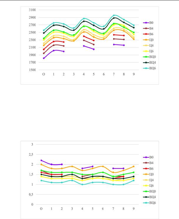
4. Comparison of experimental data with theoretical methods in vibrated, centrifuged and vibrocentrifuged reinforced concrete columns based on the standard, integral and differential characteristics of concrete. Let us now identify the load-bearing capacity of vibrated, centrifuged and vibrocentrifuged reinforced concrete columns by means of diagrammatic methods based on the standard, integral and differential characteristics of concrete according to formulas 1––17. Let us summarize the obtained calculated data on the load-bearing capacity in Fig. 3 and using the deformations in Fig. 4. The deviations in the values of the load-bearing capacity and deformability of the columns obtained by various calculation methods from the experimental value were identified and presented in Table 1 and 2.
39
Russian Journal of Building Construction and Architecture
Load-bearing capacity, kN
Calculation method
Fig. 3. Experimental and theoretical values of the load-bearing capacity of the columns calculated by means of different methods:
0 –– in experiments; 1, 2, 3 –– diagrammatic approach, iterative method based on the standard, integral, differential characteristics of concrete; 4, 5, 6 –– diagrammatic approach, an approximate method for
normative, integral, differential characteristics of concrete; 7, 8, 9 –– diagrammatic approach, a simplified method for the standard, integral, differential characteristics of concrete
Deformations, mm
Calculation method
Fig. 4. Graphical presentation of experimental results and theoretical values of column deformability calculated by means of different methods: 0––9 –– the same as in Fig. 3
The analysis of the results enabled us to draw the following conclusions.
Calculation by the diagrammatic approach according to the suggested iterative, approximate and simplified methods yielded even more indicative results. The deviations reached only
40