

5.4.4 “Hard” and “soft” dots
“Soft” or to some extent un-sharp dots, inherent in mechanicals, allowed, as was shown in figure 4.6, for the manual tone and color correction by halftone dots etching on a film. Such a facility was lost, as coming to Electronic Dot Generation (EDG), on behalf of providing the rigid connection between the image signal and resulting print tone value.3 Degree of dot “hardness” is defined in this sense according to the tolerances in the process of copying the halftone transparency on, for example, litho plate. The explained below empirical requirements to dot parameters were in this light given in 1990ies by ISO 12647.
Film based plate making is nowadays greatly replaced by the direct CtP techniques. Nevertheless such explanation isn’t out of place due to the similar development tolerances effect on the interaction of toner with un-sharp energy distribution in a latent dot image on OPC. Similar effects are also met because of non-uniform heat distribution in thermal exposing the plate layers by laser in CtP.
The dot sharpness depends on film properties, specifics of screening process (projection, contact, electronic), light scattering in the film layer and other factors. Figure 5.13 shows the examples of optical density distributions in projection (a) and electronic (b) screening, as well as the ideal П-shaped ones (c).
In these graphs Dthr – threshold density as a certain utmost value at which the radiation transmitted through the transparency is still sufficient to dampen the plate sensitive layer. For mechanicals, with respect to a litho plate making Dthr = 1.0 ± 0.2. Higher exposures were unacceptable, because, as follows from figure 5.13 (a), of the loss of small dots and, accordingly, highlight gradations. Conversely, excessive reduction of exposure, as can be seen from the same figure, was fraught with the loss of small gaps in the shadows.
|
Figure 5.13 Approximate density distributions within halftone dots for the photomechanical (a) and electronic (b) screening; with the ideal properties (c) |

The instability of the copy density can be caused by the deviations of plate sensitivity, exposure, conditions of development and other reasons. A means of controlling the magnitude and stability of exposure is the stepwise continuous tone test of 13 patches, differing by approximately 0.15 density units (at the left in figure 5.14).

Figure 5.14Test for the control of copying a halftone transparency onto a sensitized litho plate
The exposure value is set from the condition of optimal use the plate resolution. To do this, the test also contains a pairs of positive and negative concentric rings of different frequency. The exposure, in which both positive and negative rings of the highest frequency are equally clear, is considered optimal. Deviation from this value in a larger direction leads to a decrease or complete loss of thin elements on a white background due to lateral light scattering within a plate sensitive layer. On the other hand, the lower exposure entails a reduction or non-processing of small gaps that have a greater density on the film, compared with larger ones (Figure 5.13). After finding the optimal mode by trial copying with different exposures, the current control is carried out according to the number of the first stepwise scale patch worked in this mode.
Even with relatively high sharpness, the density, especially for small dots and gaps, on the transparencies obtained in different output devices, can differ significantly. In this regard, the exposure may require some adjustment when changing their type.
Lateral light scattering in the copying layer reduces the size of printed elements on the plate by 2 - 4%. This "negative" dot gain together with its other components (optical and physical) is taken into account and compensated at the prepress stage.
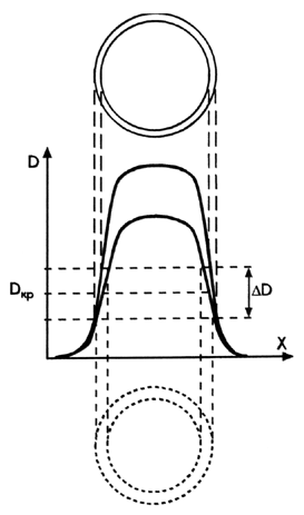
The objective criterion for the copying properties can serve as shown in Figure 5.15, the gradient of density on the front of distribution at level Dthr:
![]() 5.5
5.5
Its required value can be calculated from the permissible deviations of achromatic or color tone values of the halftone print through the corresponding changes in the dot areas.
|
Figure 5.15 The higher the dot densitogram gradient at Dthr level (a), the less deviations of the printing element size on the plate (b) within the tolerance for the copying process stability
|

At the same steepness of a distribution front the copying instability more significantly impacts on the small dots area. Therefore, the requirements to dot sharpness become tougher with increasing the regular halftones ruling, as well as with stochastic screening for its fine dots are involved in the gradation transfer across the whole tone range.
Transparency parameters, set out in the first and second ISO 12647 versions [2.8; 2.9; 3.19] illustrates the graph in figure 5.16. It shows the advised densities of fog+base, solids, dots and gaps.
To avoid the plate "shading", the open areas density is limited to 0.15, and the gaps between the dots to 0.25. As can be seen from the same graph, the standard assumes that if the density in the solid area reaches 3.5 units, then in the “core density” within dot it will be at least 2.5, and in small ones it will reliably exceed the threshold. These recommendations are based on the properties of transparencies, which were obtained in the past by means of projection or contact Halftoning, where the density of small dots barely reached the threshold Dthr as was shown in figure 5.13 (a).
|
Figure 5.16 The parameters of the halftone transparencies in terms and values of ISO 12647 |

Stability of a dot area in the copying process the standard estimates by the width of dot fringe which should not exceed 1/40 of the screen period. However, the expression 5.5 defines these properties more explicitly than sharpness. This is explained by examples of distributions for two dots having the same fringe width (Figure 5.17). Despite that, a dot with a higher optical density is reproduced on the plate with a smaller area deviation due to its higher gradient at the threshold level Dthr. Hence, it becomes clear why some of vendors promote their filmsetter with focus on providing a density of 5 (and even 6!) units, i.e., many times greater than Dthr [5.27].
|
Figure 5.17 The halftone dot with the same fringe width, but higher density is more stable in the plate making The high density of dots is achieved in the output device at the cost of a compromise in meeting such fundamentally important requirements as resolution and performance. To increase the optical density, for example, from two to three units at the same light source power or film sensitivity, it is possible either by reducing the recording speed tenfold, or, if it is saved, by reducing the number of recorded lines and, accordingly, the output resolution. The above connection of the exposure distribution with the tone value stability is also typical for the halftone image formation by means of electrophotography and, to a certain extent, by the thermal effect of laser radiation on the plate layers in CtP.4 In conclusion, it should be noted that the dot sharpness is in no way the sharpness of the halftone image itself, although reasoning based on the premise of the inverse of this seemingly obvious position is met in some brochures.
|
Key summary issues
The choice of image input device is determined by the type of print product, characteristics of the used graphic originals and printing technology.
There are scanning systems that use mechanical movement on both or one of the coordinates, as well as electronic, without such movements.
The resolution of scanning the original is directly related to the scale and the screen ruling of the print.
Reduction of the scan spot in relation to the image sampling step is fraught with noise in the received signal, while excessive overlapping of this step by the spot leads to the image defocusing.
The volume of the signal to be processed grows quadratically with the increase in the print dimensions and its screen ruling.
By the type of spectral sensitivity of color channels scanners and digital cameras are mostly densitometers, not colorimeters.
Obtaining intermediate and final copies is characterized by many features that are differently combined in a wide variety of technologies used.
Electro-mechanical engraving is effective in the cylinders preparation for gravure printing.
For the manufacturing of various types of copies, the broad number of impacts on different substrates is used.
Digital printing has a number of fundamental advantages, but at the same time, it does not cover all the possibilities of traditional one.
Parameters of films and plates recorders are largely determined by the scheme of their scanning system.
Halftone transparency - one of the intermediate representations of the required ink coverage, and therefore its properties should provide a non-ambiguous transition of this value on the plate.
The threshold copying density (Dthr) is limited due to the threat of small dots loss due to lateral light scattering in the plate sensitive layer.
Summing up the exposure distributions of adjacent lines in recording on sensitive surface leads to some increase of the dot size and gaps decrease.
Tests
5.1 The dichroic mirror performs the following function:
a) selectively absorbs the incident light, reflecting the rest of it;
b) divides the incident light spectra into two parts;
c) passes the entire unabsorbed part of the incident light.
5.2 The color separation function is not performed by an optical element such as:
a) dichroic mirror;
b) beam-splitting mirror;
c) prism;
d) diffraction grating;
e) coloured glass.
5.3 The light source of the reproduction system is not characterized by such a parameter as:
a) light output;
b) spectral characteristic;
c) dark current;
d) monochromaticity;
e) coherence.
5.4 Among the requirements for the photoelectric transducer (PET) there is no requirement of:
a) spectral sensitivity;
b) integral sensitivity;
c) noise level;
d) light output;
e) power consumption.
5.5 The light sources for image capturing with the color separation do not apply:
a) laser;
b) LED;
c) CRT;
d) incandescent lamp;
d) gas-discharge tube.
5.6 The photoelectric transducer (PET) of the scanning device is not:
a) CCD array;
b) photodiode;
c) PMT;
d) LED array.
5.7The widest range of the light sensitivity has:
a) PMT;
b) CCD;
c) photoresistor;
d) digital camera.
5.8 The technical characteristic of the scanner is not:
a) resolution;
b) screen ruling;
c) ADC bit depth;
d) the number of optical channels.
5.9 The choice of scan spot size for the image input is based on the:
a) resolution of the output device;
b) screen ruling of the print;
c) available scanner resolution;
d) scanner ADC bit depth.
5.10 Taking into account the screen ruling (L) and reproduction scale (M), the scan lines density of the image input is set as:
a) LM;
b) L/M;
c) 2LM;
d) 2/(LM);
e) 1/(2LM).
5.11 Non-uniform sensitivity of the CCD array elements in the flatbed scanner is compensated by:
a) inverted signal of "white";
b) adjustment of the copy illumination;
c) filter of variable density.
5.12 The sampling area greater of theoretical is used for:
a) tone rendition improvement;
b) object moiré suppression;
c) increase of definition;
d) image sharpening.
5.13 The use of the image sampling area much less of theoretical leads to:
a) smooth tone rendering;
b) noise;
c) distortion of contour geometry;
d) increase of contrast.
5.14 The signal value at the photo sensor output is closer to the following parameter of a scanned original:
a) optical density;
b) saturation;
c) reflection;
d) lightness.
5.15 The principal advantage of the computer-to-print technology compared to the traditional is the ability to:
a) quality improvements;
b) personalization;
c) speed increase;
d) reducing the prints cost.
5.16 The smallest dimensional matching of the color separations is provided by the output devices of the type:
a) capstan;
b) in-drum;
c) on-drum.
5.17 The least convenient in terms of automation the exposed material installation and removal are output devices of the type:
a) capstan;
b) in-drum;
c) on-drum.
5.18 Multibeam (parallel) lines recording is used in the on-drum scanners:
a) enhancing the resolution;
b) reducing the drum rotation speed;
c) increasing the accuracy of the lines laying.
5.19 The exposure value in the copying on a litho plate is set according to:
a) recommended optical density (patch number) of the reference grayscale;
b) dot density of the copied transparency;
c) fog+base density of the transparency;
d) achieving the maximum resolution on the plate;
e) density of solid on the transparency.
5.20 The stability of the dot area transfer onto the plate is most accurately characterized by one of the following properties of transparency:
a) density gradient at the copying level;
b) difference between the densities of dot and blank area;
c) dot fringe width.
1 In the visually perceived world this range is 9 to 10 orders of magnitude. Accordingly, due to the mechanism of brightness adaptation, the vision sensitivity changes millions of times.
2 .Its correction in the subsequent stages of the mechanicals, plates and prints manufacture indicates only the lack of rigorous normalization or irrational organization of the whole process.
3 Based on the consumer’s habit to have the possibility of “last moment” manual correction, some scanner vendors intentionally equipped their first EDGs with the patented means of dot edges defocusing.
4 The interaction of such distributions with each other, when touching neighboring dots is considered in the eighth chapter in relation to the TVI effect on the tone rendition.