

Power Flow Control of DC Power Distribution Systems using Triple Active Bridge Converter in a Data Center
Yue Yu |
|
|
Tokyo Metropolitan Unicersity, |
Keiji Wada |
Yuichi Kado |
Tokyo, Japan |
Tokyo Metropolitan Unicersity, |
Kyoto Institute of Technology, |
yu-yue1@ed.tmu.ac.jp |
Tokyo, Japan |
Kyoto, Japan |
|
kj-wada@tmu.ac.jp |
kado@kit.ac.jp |
Abstract—In recent decade, the demand for power distribution system in data centers are significantly climbed, while the requirements for advanced power flow control for DC power distribution systems are in urge needed. This paper presents higher-reliability DC power distribution systems using a triple active bridge (TAB) converter that can be applied in a data center, and it will be shown a power flow control among the three DC power distribution systems. The TAB converter is composed of three DC/AC converters connected via a transformer, and has ability to transmit the power to arbitrary directions. This paper proposes DC power distribution systems for data center using the TAB converter for balancing the power from the voltage sources.
The feature of this system has no batteries. Then, the power flow
control with closed-loop feedback control and the load balancing control are explained for adjusting the unbalanced load condition in data centers. The simulation designed the operation of DC power distribution system using 380V TAB converter in data center, and the power flow control for the power distribution system. From these results, the performance of the power flow control is confirmed, while the functional behavior of proposed three DC power distribution systems using the TAB converter is proved.
Keywords—DC power distribution system, Load balancing control, Power flow control, Triple active bridge converter.
I.INTRODUCTION
During the past decade, the electrical consumption of commercial power system has been accelerated due to the development of global cloud-computing, big data and largescale technology companies has brought a rapid increase demand of data centers[1]. Expanded data centers require high demand of energy[2], the data center servers and infrastructure has depleted estimated 7% of the global electricity power. In addition, the electric power consumed by US data centers is estimated to increase about 10% annually [3] [4]. On the other hand, those surveys and reports revealed the brutal realities of the fact that conventional data centers are still relying on the fossil energy sources for power supply, such as oil and natural gas, has raised concentrated concerns in environmental problems and pollution preventions. Under this condition, the effective and high reliable power distribution system that can improve the performance and save the energy imperatively needed.
Fig.1. Conventional power distribution system in a data center.
In the majority of data centers being used recently, a traditional power distribution system is as shown in Fig.1, where input voltage source must past through multiple conversion stages from the AC input source. The Power Distribution Units (AC/DC and DC/DC) converts to DC voltage source that can be utilized by the ICT (Information and Communication Technology) equipment and servers in the data center. The AC to DC conversions are necessary because the data center loads are used in only DC voltage. These power conversion procedures result in energy wasted during not only the power conversion, but also in the cooling. Deploying the DC power distribution system in the data center replace of the traditional AC is an effective way to reduce unnecessary conversions, energy losses, and lower energy costs [5]-[7]. In the traditional power distribution system, the backup system such as the batteries are necessary, so that the data center would not be affected by the interruptions[8]. However, the volume and cost of conventional batteries is too much large, so realize of a highly efficient DC power distribution systems that do not use a battery is required.
Among the many levels of voltage bus in the DC distribution systems, [9] [10] introduced the benefit of selecting 380V DC voltage as the transmission bus voltage in the power distribution system. Compare with the traditional AC power distribution system, 380V DC provides obvious advantages such as higher reliability, higher efficiency, lower cost and volume, make the 380V DC distribution system the most potential choice.
A great number of research institutes and companies are now attempting to develop the products can be applied in 380V DC distribution applications[11][12]. In addition, industrial standards for deploying the level of 380V DC power systems have been published, which designated the bus voltage between 260 and 400V[13].
978-1-5386-6705-7/18/$31.00 ©2018 IEEE
Researchers and engineers have been investigating a triple active bridge (TAB) DC-DC converter with an isolation function configuration that can be used for power distribution [14][15]. The TAB converter consists of three independent active H-bridge cells with external inductances and connected via a three-winding high-frequency transformer. The DC power distribution system that uses a TAB converter has been introduced and its advantages have been described [16]. In addition, DC power can be controlled to three-direction.
This paper proposes DC power distribution systems using a TAB converter for a data center without any batteries, as shown in Fig. 2. The power flow control that can solve the situation of inconstant demand of load power in data centers and achieve the load balancing function. By using the TAB converter, when one load power of the DC distribution systems is decreased, the TAB converter can react to the power balancing in each DC power supply. The feedback control of load balancing control and input power balancing is discussed. The simulation results for the power distribution in data centers with full load and half load condition, using the power flow controlled TAB converters. The simulations results show the operation of the power flow control for DC power distribution systems with inconstant power demands in a data center, and the behavior of the proposed structure.
.
II.MODELING THE POWER DISTRIBUTION SYSTEM USING
THE TAB CONVERTER.
A. Topology of the TAB Converter
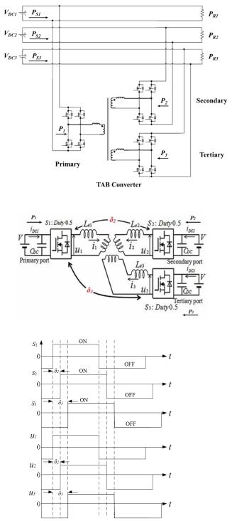
The topology of TAB converter is consist of three active H- bridge converter cells that are connected via a three-winding transformer, as can be seen from the Fig.3. In the TAB converter, fsw represents the switching frequency, while the inductances, Le1, Le2, and Le3 are the external inductors connected to the AC side in each port. The each AC-side voltage waveform is square waveform, and the duty ratio is set to 50%. The primary, secondary, and tertiary side of the TAB converter can be connected to DC voltage source, and the power transmit among the three sides through the transformer can be achieved only the phase shift control. The each DC voltage is assumed to constant, and that is the same as the DC distribution. The phase shift difference of the gate signals between the primary side and the secondary side is represented by δ2 [rad], while the signal between the primary side and the tertiary side is represented by δ3 [rad] as shown in Fig. 4.
B. Phase Shift Control for the TAB Converter
After defined the phase shift of the TAB converter, the phase shift control is utilized in the power distribution system. Fig.4. shows the phase-shift pattern and the operation under the phase shift control. Here, S1 to S3 are the gate signals of each active bridge converter and u1 to u3 are each the AC side voltage.
In the TAB converter, the total power flow in the system through the transformer yields to the following formula:
= 0 |
(1) |
Fig. 2. Diagram of DC power distribution system using the TAB converter in data center.
Fig. 3. Topology of the TAB converter.
Fig. 4. Phase-shifting waveforms of the TAB converter.
The relational expression of power flow P1, P2, P3, and the phase shift δ2, and δ3 can be derived, and follows the equations when under the condition of same DC input voltage and external inductance:

Fig.5 Closed-loop feedback control of the power control for the TAB converter.
When 0 ≤ |
( |
≤ |
) |
: |
( |
) |
|
|
|
= |
|
|
|
|
|
|
|
) |
|
|
( |
|
) |
( |
|
)( |
(2) |
||
= |
|
( |
|
) |
( |
|
)( |
) |
|
When= |
|
|
|
|
|
|
|
|
|
|
|
≤ |
|
: |
|
|
|
|
|
0 ≤ |
|
|
|
|
|
|
|
||
= |
|
( |
|
) |
|
( |
) |
|
(3) |
= |
|
( |
|
) |
( |
|
)( |
) |
|
= |
|
( |
|
) |
( |
|
)( |
) |
|
As shown from (2) and (3), when the circuit parameters are fixed, the power flows of the TAB converter can be controlled using the phase shift control.
C. Power Distribution System using the TAB Converter.
Based on the characteristic of the TAB converter, a DC power distribution system using the TAB and applied with DC power source was constructed for three DC distribution systems as shown in Fig.2. In the power distribution system, the resistive loads in the terminal of the power racks represent the servers and other ICT equipment of a data center, while the DC sources VDC supplied input power for each load in the data center [17]. In the normal operation of a data center, the input DC sources, VDC1,
VDC2, and VDC3 directly provide power to be used by the loads, without applying the TAB converter.
In the power distribution system, the TAB converter is employed as a power router. Under the situations of increasing and decreasing demand of the resistive loads, as well as the full load and the half load that may happen in the data center, the requirement of the DC transmission among the power racks are necessary. By using the TAB converter and the power flow control, the power balancing operations from each DC power supply can be achieved.
III.POWER FLOW CONTROL FOR THE DC POWER
DISTRIBUTION SYSTEM
A. Closed-loop Feedback Control
In the operation of the power flow control for power distribution system using the TAB converter, an accurate control
method is needed to supervise the amplitude of the power transmitted to the resistive load, during the full and half load situation. In this section, the closed-loop feedback control based on phase shift control is demonstrated for the DC power distribution system.
The procedure of closed-loop phase shift control is shown in Fig. 5, where P2*, and P3* represent the reference power for the TAB converter in secondary and tertiary side. When the power transmission of the power distribution system is varied, the TAB converter act as the function of the power router, to deliver the changing value of power through the transformer. When the reference values of P2*, and P3* are changed, by using the feedback phase shift control and the feedback of the real time voltage, the output power P2, and P3 could be regulated in term of the reference value.
According to (2) and (3), it is clear that by changing phase shift δ2 and δ3, power transmitted in three sides of the TAB converter P1, P2 and P3 will be controlled, and so as the DC current I2 and I3 of the secondary and tertiary sides. When directly change the transmitted power of the secondary side, the power amplitude in the tertiary side will also be disturbed as well as the control accuracy.
Under this situation, a decoupling phase shift control is necessary for the TAB converter and the power distribution system. In this closed-loop feedback control, a decoupling matrix is constructed for this situation, and applied by defining the off-diagonal elements of the matrix, so that the decoupling control can be obtained [18].
First, derive a matrix to express the DC currents of primary and tertiary side and the phase shift angle:
= |
= |
(4) |
Then, by introducing a suitable matrix [ ] for the variation of phase shift of δ2’, δ3’:
= |
= |
(5) |
Rearrange the (4) and (5), the expression of phase shift variation and DC currents is:
|
= |
= |
(6) |
|
After that, use an appropriate matrix [ |
] that satisfies [ ] [ ] |
|
= |
[1, 1]; thus, the matrix [ ] is the inverse of the matrix |
||
[ ], and the off-diagonal elements of the input-output characteristic by the operation can be set to 0:
= |
( )( − |
) |
|
(7) |
( )( − |
) |
) |
|
|
= |
|
( )( − |
(8) |
|
|
( )( − |
) |
|
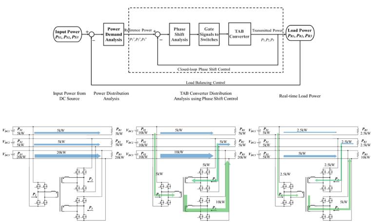
Fig.6. Diagram of power flow control in the power distribution system using the TAB converter.
Fig.7 Power flow diagram during the three simulation periods.
In this condition, ( ) represents a controller such as proportional or integrations. Therefore, by properly build up a closed-loop control matrix of phase shift variation δ2' and δ3', the phase difference in δ2, δ3 will not interfere with each other when controlling the P2 or P3. From the above equations, the schematic of closed-loop feedback control is shown in Fig. 5, the phase shift δ2, δ3 can be determined independently for controlling the power transmitted in the power distribution system.
B. Load Balancing Control
Power management of the power distribution system in data center is becoming an increasingly important method for improving the total system efficiency. An effective power management contribute to correct the operation during the power variation in the data center. In addition, the power management can also distribute to adjust the demand among data center racks so that the electric load balancing is ensured.
In this paper, the load balancing control that can analyze the power demand of the load power, and accordingly evaluate the power distribution in each rack, thus save the power in the power distribution system is proposed. The power balancing condition of the DC power distribution system follows the equations below:
= = ( |
− |
)/3 |
(9) |
= |
− |
|
|
Where, P2*, and P3* mean the power reference for each power in the TAB converter. From (9), it is clear that, the power transmitted in the TAB converter is determined by the real time load power and the input power in each power rack. By using the control of the load balancing, the input power of the DC power distribution system can be balanced, while the TAB converter could transmit the power among the power racks by using the phase shift control. Based on the mentioned derivation of the power flow control, a diagram of power flow control method is proposed, as shown in Fig.6, consists of the closedloop phase shift control and the load balancing control. When the load power in the terminal of the DC power distribution system is varied during the full or half load operation, the load balancing control diagram detects the power demand and command to the TAB converter, therefore the power transmission in the power distribution system is accordingly adjusted with the help of the TAB converter.

IV. SIMULATION RESULTS
In order to confirm the power flow control for the DC power distribution system using the TAB converter, the simulations are conducted during the full load and half load condition, using the 380 V DC grid input. The simulation model of power distribution system using the TAB converter is based on the Fig.2. The resistors at the end of the distribution system represent the resistive loads in a network system, such as servers or the IT load, which are consuming inconstant amount of power according the demand. The phase shift control for TAB converters are applied in the simulation. The Powersim (PSIM) simulation model was constructed based on Fig.2.
TABLE I. PARAMETERS OF THE 380 V TAB CONVERTER FOR A DC
POWER DISTRIBUTION SYSTEM.
|
DC voltage |
|
380 V |
|
Switching |
|
15 kHz |
|
|||
|
VDC |
|
|
|
frequency |
|
|
||||
|
|
|
|
|
|
|
|
|
|||
|
External |
|
|
|
Transformer |
|
|
|
|
||
|
|
43.47 µH |
|
leakage |
|
1.1 µH |
|
||||
|
inductance |
|
|
|
|
||||||
|
|
|
|
inductance |
|
|
|
|
|||
|
|
|
|
|
|
|
|
|
|
||
TABLE II. |
SIMULATION PARAMETERS, FOR THE 380V TAB CONVERTER |
||||||||||
|
|
|
IN THE POWER DISTRIBUTION SYSTEM. |
|
|
|
|||||
|
|
|
|
|
|
|
|
|
|
||
|
|
|
|
Full load |
|
Full load |
|
Half load |
|||
|
|
|
|
w/o TAB |
|
with TAB |
|
with TAB |
|
||
|
P1 |
|
|
0 |
|
5 kW |
|
|
2.5 kW |
|
|
|
|
|
|
|
|
|
|
|
|
||
|
P2 |
|
|
0 |
|
5 kW |
|
|
2.5 kW |
|
|
|
|
|
|
|
|
|
|
|
|
||
|
P3 |
|
|
0 |
|
10 kW |
|
|
5 kW |
|
|
|
|
|
|
|
|
|
|
|
|
||
|
PS1 |
|
|
5kW |
|
10kW |
|
|
5kW |
|
|
|
|
|
|
|
|
|
|
|
|
||
|
PS2 |
|
|
5kW |
|
10kW |
|
|
5kW |
|
|
|
|
|
|
|
|
|
|
|
|
||
|
PS3 |
|
|
20kW |
|
10kW |
|
|
5kW |
|
|
|
|
|
|
|
|
|
|
|
|
||
|
PR1 |
|
|
5 kW |
|
5 kW |
|
|
2.5 kW |
|
|
|
|
|
|
|
|
|
|
|
|
||
|
PR2 |
|
|
5 kW |
|
5 kW |
|
|
2.5 kW |
|
|
|
|
|
|
|
|
|
|
|
|
||
|
PR3 |
|
|
20 kW |
|
20 kW |
|
|
10 kW |
|
|
|
|
|
|
|
|
|
|
|
|
|
|
After built the DC power distribution system using the 380V TAB converter with the power flow control, the simulation condition is designed as shown in Table 2, within the three periods, the unbalanced full load period, the balanced full load period, and the balanced half load period.
Fig.7 shows the power flow schematic during the three period: full load without TAB converter operation, full load with TAB converter, and half load with TAB converter. Fig. 8 shows the simulation results of the power distribution system using the 380V TAB converter under the power flow control. In the first period, the power distribution system is under the unbalanced full load operation, without using the TAB converter and power flow control. Due to the different load power, the input power flows of PS1, PS2, and PS3 are under the unbalanced condition, delivered 5kW, 5kW, and 20kW to the resistive load. In the second period, when the load balancing control is applied, by using the TAB converter, the power flow of PS1, PS2, and PS3 are adjusted to the same amplitude of 10kW, ensured the balance power in the power distribution system during the balanced full load. In the same time, each of PS1 and PS2 transmitted 5kW power to the PS3 through the TAB converter.
Fig.8. simulation results of the power distribution system using the 380V TAB converter under the power flow control.
During the last period, when the load power in the resistive loads is decreased into half load, the , the power flow of PS1, PS2, and PS3 are adjusted to the amplitude of 5kW, while PS1 and PS2 transmitted 2.5kW power to the PS3 through the TAB converter, make sure the half power of the PR3 is ensured. The waveforms of the power flow in the rack of PS1, PS2, and PS3 is managed to change from the unbalanced to the balanced amplitude by using the power flow control, and the power from the input source can be saved when the load is decreased from the full load to the half load. Further, from the waveform of PR1, PR2, and PR3, it is clear that the load power consumed by the users is guaranteed during the full load and half load operation.
V. CONCLUSION
This paper proposed DC power distribution systems using the TAB converter, for realizing a high-reliability data center. The power management using the closed-loop control and load balancing for the DC power distribution system is proposed. The simulation is designed considering the full and half load during the operation in a data center, and has been conducted. The simulation results show the simulation model is tested under the power flow control. The satisfactory performance in simulation waveforms validated the feasibility of applying the power flow control in the DC power distribution system with TAB converter, and proved the proposed system and power flow control method is available for the operation in a wellperformance system in the data centers.
REFERENCES
[1]R. Brown et al., “Report to congress on server and data center energy efficiency: Public law 109-431,” Lawrence Berkeley National laboratory, Tech. Rep., 2008.
[2]Apple, Facebook, and Google Top Greenpeace Energy Report, http://fortune.com/2017/01/10/greenpeace-energy-report-apple-facebook- google/
[3]NRDC, “Data Center Efficiency Assessment”, https://www.nrdc.org/energy/files/data-center-efficiency-assessment-IP.pdf.
[4]M. Pedram, “Energy-efficient datacenters”, Computer-Aided Design of Integrated Circuits and Systems, IEEE Transactions on, vol. 31, no. 10, pp. 1465–1484, 2012.
[5]D. Dong, I. Cvetkovic, D. Boroyevich, W. Zhang, R. Wang, and P. Mattavelli, “Grid-interface bidirectional converter for residential DC distribution systems—Part one: High-density two-stage topology,” IEEE Trans. Power Electron., vol. 28, no. 4, pp. 1655–1666, 2013..
[6]M. Tabari, A. Yazdani “An Energy Management Strategy for a DC Distribution System for Power System Integration of Plug-In Electric Vehicles”. IEEE Transactions on Smart Grid, 2016, pp. 659 - 668.
[7]A Hatami, M R Tousi, P Bayat, et al, “Power management strategy for hybrid vehicle using a three-port bidirectional DC-DC converter,” IEEE 23rd Iranian Conference on Electrical Engineering (ICEE), pp. 14981503, 2015.
[8]Izabela Stepniak, Aleksander Ciszewski, “Grafting effect on the wetting and electrochemical performance of carbon cloth electrode and polypropylene separator in electric double layer capacitor”, Journal of Power Sources,2010, Volume 195, Issue 15, Pages 5130-5137.
[9]Guy AlLee, William Tschudi, “Edison Redux: 380 Vdc Brings Reliability and Efficiency to Sustainable Data Centers”, IEEE Power and Energy Magazine, Vol: 10, pp.50-59, 2012.
[10]M.H. Ryu, H.S Kim, J.W. Baek, “Effective Test Bed of 380-V DC Distribution System Using Isolated Power Converters”, IEEE Transactions on Industrial Electronics, pp: 4525 – 4536, 2015.
[11]EMerge Alliance Data/Telecom Center Standard, www.EMergeAlliance.org.
[12]Neil Rasmussen, “AC vs. DC Power Distribution for Data Centers”, [Online]: http://www.apc.com/salestools/SADE-5TNRLG/SADE- 5TNRLG_R6_EN.pdf.
[13]Wilfried Schulz, “Overview to ETSI Standards and Guides for Efficient Powering of Telecommunication and Datacom Equipm ent and Building”,
Telecommunication - Energy Special Conference (TELESCON), 2009.
[14]Y Kado, D Shichijo, K Wada, K Iwatsuki, “Multiport power router and its impact on future smart grids”, Radio Science, vol. 51, no. 7, pp. 1234-1246, 2016.
[15]Yue Yu, K.Masumoto, K. Wada, Y. Kado. "A DC Power Distribution System in a Data Center using a Triple Active Bridge DC-DC Converter", IEEJ Journal of Industry Applications, Vol.7 No.3 pp.202–209.
[16]Yue Yu, K.Masumoto, K. Wada, Y. Kado. "Power flow control of a triple active bridge DC-DC converter using GaN power devices for a low-voltage DC power distribution system", International Future Energy Electronics Conference and ECCE Asia (IFEECECCE Asia), 2017.
[17]H. Wang, J. Huang, X. Lin, “Exploring smart grid and data center interactions for electric power load balancing”, ACM SIGMETRICS Performance Evaluation Review, 2013, Vol:41, Issue 3, pp: 89-94.
[18]C. Zhao, S. D. Round, and J. W. Kolar, “An isolated three-port bidirectional DC-DC converter with decoupled power flow management,” IEEE Trans. Power Electron., vol. 23, no. 5, pp. 2443–2453, Sep. 2008.