

1
Control of DC power distribution system of a hybrid electric aircraft with inherent overcurrent protection
A-C. Braitor, A.R. Mills, V. Kadirkamanathan
and G.C. Konstantopoulos
Dept. Automatic Control and Systems Engineering
The University of Sheffield
Sheffield, UK
{abraitor1,a.r.mills,visakan,g.konstantopoulos}@sheffield.ac.uk
ABSTRACT—In this paper, a novel nonlinear control scheme for the on-board DC micro-grid of a hybrid electric aircraft is proposed to achieve voltage regulation of the low voltage (LV) bus and power sharing among multiple sources. Considering the accurate nonlinear dynamic model of each DC/DC converter in the DC power distribution system, it is mathematically proven that accurate power sharing can be achieved with an inherent overcurrent limitation for each converter separately via the proposed control design using Lyapunov stability theory. The proposed framework is based on the idea of introducing a constant virtual resistance at the input of each converter and a virtual controllable voltage that can be either positive or negative, leading to a bidirectional power flow. Compared to existing control strategies for on-board DC micro-grid systems, the proposed controller guarantees accurate power sharing, tight voltage regulation and an upper limit of each source’s current at all times, including during transient phenomena. Simulation results of the LV dynamics of an aircraft on-board DC micro-grid are presented to verify the proposed controller performance in terms of voltage regulation, power sharing and the overcurrent protection capability.
I. INTRODUCTION
N the last few years, the hybrid electric aircraft initiative Ito combine conventional and electrical systems in aircrafts has significantly increased. This has stemmed from the need to improve efficiency and reliability [1], and to reduce emissions and lifetime operating costs of the aircraft. More recent models, such as Boeing 787 and the Airbus A380 [2], [3], have more electrical power components installed compared to older models, and this trend is expected to increase further in the future. As a result, a reliable and resilient power distribution system in an aircraft is of major importance and since it represents an isolated system with generators, power converters and loads, it can be regarded as an on-board microgrid system, often of DC nature. Hence, with increased onboard power generation, the challenge of controlling and managing multiple sources that meet the increasing demand in the power distribution system arises.
On-board DC micro-grids with enhanced reliability that do not use communication among the units, often operate in a distributed control manner where the control method for each unit is based on the available local variables. Control methods employed in aircraft applications that do not require communication links but rely on optimization techniques have also
P.J. Norman and C.E. Jones
Dept. Electronic and Electrical Engineering
University of Strathclyde
Glasgow, UK
{patrick.norman,catherine.e.jones}@strath.ac.uk
been proposed in [4], [5]. A cascaded control structure with an outer loop has been adopted in [6] to prevent instabilities in the case of small output filters. Thus, overall system stability needs to be guaranteed by the sources that operate in parallel with a simulataneous tight control of the voltage bus. The most common employed technique for regulating the voltage of DC/DC converters uses traditional single or cascaded PI controllers [7], [8]. Based on linearization and the smallsignal model of the converter, traditional PI controllers can be designed to ensure local stability of the desired equilibrium point. However, the nonlinear dynamics of the converter indicate a need for advanced control strategies that can be applied directly to the nonlinear model of the system, such as sliding control [9], [10] or passivity-based control [11], [12]. Such control strategies can guarantee nonlinear closed-loop stability based on strong mathematical background; however, in most cases they require global information of the system or load parameters that may change during the system operation.
The main challenges and problems of an on-board HEA DC-based system are the voltage stability and regulation, the power flow management and power sharing and the highly dynamic characteristics of the network [13]. Since modern load types introduce complex nonlinear dynamics that can complicate the existing system nonlinearities and increase the number of states of the overall system, there is a clear interest in designing more advanced controllers that can act independently from the system parameters and can also ensure stable operation of the converter at all times. Particularly, an overcurrent protection that limits the inductor current below a given value is of critical importance to protect the converter during fast transients or unrealistic power demands. The occurence of transients is very common, since the dc/dc converters operate with high switching frequencies to increase the power density. Furthermore, it is known that the switching frequency is proportional to the partial discharge [14]. Therefore, to mitigate these effects, a defined range for the switching frequency is usually selected for aircraft applications [15], [16], [17].
Even during fast transients, the current limitation, as defined in [18], [19], can protect equipment without violating the boundaries set by the technical specifications of the converters. Despite the converter being protected by protection devices
978-1-5386-4192-7/18/$31.00 ©2018 IEEE
2
|
|
EXT |
|
EXT |
|
|
|
|
PWR |
|
PWR |
|
|
|
|
|
SSB |
|
|
|
|
HV BUS |
|
|
|
HV BUS |
|
BTB |
BTB |
|
APU |
BTB |
|
BTB |
|
|
|
||||
|
|
LOAD |
GEN |
LOAD |
|
|
|
DC |
|
DC |
|
||
DC |
AC |
|
DC |
|
AC |
DC |
|
|
|
|
|
||
AC |
|
|
DC |
|
|
AC |
|
|
|
|
|
||
|
G |
|
LV BUS |
G |
|
|
G |
|
|
|
|
|
G |
|
|
DC |
|
DC |
|
|
|
|
DC |
|
DC |
|
|
|
|
FUEL CELL |
|
BATTERY |
|
|
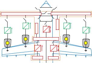
Figure 1. Typical topology of an on-board DC micro-grid of a hybrid electric aircraft
(e.g. additional fuses, circuit breakers and protection relays), there is ongoing desire towards guaranteeing overcurrent protection via the control design [20]. Existing traditional strategies can effectively change the original control structure to the overcurrent protection control structure [21]. However, since closed-loop stability cannot be analytically proven, the initiative to design a control structure suitable for all the aforementioned tasks is still of significance.
A nonlinear control scheme that acts regardless of the system and load parameters is proposed in this paper to guarantee voltage regulation and power sharing with an overcurrent protection for both unidirectional and bidirectional boost converters for a hybrid electric aircraft on-board DC micro-grid. The new concept adopts the droop control methodology to gurantee power sharing without communication and resides on the idea of applying a constant virtual resistance in series with the converter inductor and a virtual controllable voltage which varies according to a nonlinear dynamical system. Using input-to-state stability (ISS) theory [22], it is demonstrated that based on a suitable selection of the controller parameters, the inductor current of each converter will never violate a maximum limit imposed by the technical specifications, regardless of the droop control regulation scenario. Hence, the converter is protected against overcurrents at all times since the power injected by the sources is always limited, even in the case of an unrealistic scenario where the power demand could exceed the capacity of the converter. This offers a superiority with respect to existing cascaded control methods with saturation units, since the proposed controller limits the converter currents during transients, not only at the steady-state, and is based on a rigorous nonlinear theory that facilitates the stability of the entire system. Extensive simulations are carried out and presented to test the desired operation of the onboard DC micro-grid and its protection against overcurrents.
The remainder of this paper is organised as follows. In Section II the on-board DC distribution network under consideration is introduced and analyzed. Section III contains a brief description of the conventional droop control and the main challenges in a DC micro-grid, followed by the controller design and proof of the overcurrent protection introduced by
each converter in Section IV. Simulation results of the onboard DC power distribution system are shown in Section V and, finally, the conclusions are drawn in Section VI.
II. NONLINEAR MODEL OF THE ONBOARD LV DC
MICRO-GRID
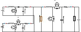
In Fig. 1, a candidate on-board DC-based micro-grid architecture for a hybrid electric aircraft is shown, represented by various types of sources connected in parallel to a common DC bus, interfaced by DC/DC and AC/DC power converters. This paper is focused on the control of the low voltage (LV) DC side of the network, which is the highlighted part in Fig. 1, and includes the integration of the LV with the high voltage (HV) bus, a battery and a fuel cell unit. In Fig. 2, the detailed LV DC configuration of the on-board DC micro-grid system is depicted consisting of two DC/DC boost converters (one unidirectional and one bidirectional) connected in parallel and feeding a common low-voltage (LV) load, and another bidirectional boost converter that feeds a HV load and links the LV bus with the HV bus. Using Kirchhoff laws and average analysis [23], the dynamic model of the entire system that includes the nonlinear behaviour of the boost converters becomes
˙ |
= |
UF C − (1 − uF C ) VF C |
(1) |
LF C iLF C |
|||
˙ |
= |
(1 − uF C ) iLF C − ioutF C |
(2) |
CF C VF C |
|||
˙ |
= |
UBAT − (1 − uBAT ) VBAT |
(3) |
LBAT iLBAT |
|||
˙ |
= |
(1 − uBAT ) iLBAT − ioutBAT |
(4) |
CBAT VBAT |
|||
˙ |
= |
VLV − (1 − uHV ) VHV |
(5) |
LHV iLHV |
|||
˙ |
= |
(1 − uHV ) iLHV − ioutHV |
(6) |
CHV VHV |
Here LF C , LBAT and LHV are the boost converter inductances (H), CF C , CBAT and CHV represent the output capacitors (F ), while the output line impedances are introduced by the resistances RF C , RBAT and RHV (Ohms). The lowvoltage and high-voltage loads are represented as RLV and RHV respectively. The state vector of the system consists of
the inductor currents iLF C , iLBAT and iLHV in the input of every converter and the output voltages VF C , VBAT and VHV
(V). The control input vector consists of the duty-ratio inputs of each converter uF C , uBAT and uHV , which by definition should remain bounded in the set [0, 1]. The DC input voltages of the converters are given as UF C , UBAT and UHV , and represent constant inputs for the system, as shown in Fig. 2.
It can be observed that system (1)-(6) is nonlinear, since the control inputs uF C , uBAT and uHV are multiplied with the system states. By considering a steady-state equilibrium (ieLi, Vie) corresponding to a duty-ratio uei , where i represents the appropriate converter for the fuel cell (F C), battery (BAT ) and for the link to the HV bus (HV ), it results from
(1), (3) and (5) that ue |
= 1 − |
UI |
, which shows that when |
|
E |
||||
i |
|
V |
I |
|
ui = 1 the inductor current continuously increases, thus the
system becomes unstable. Imposing a given upper bound for the inductor current is of major importance that should be guaranteed at all times to achieve permanent device protection. Such a controller, equipped with this capability while also
|
|
|
|
|
|
UHV |
ILFC |
LFC |
|
RFC IOUTFC |
ILHV LHV |
RHV IOUTHV |
|
UFC |
UFC |
CFC |
VFC |
|
|
|
|
|
LV LOAD |
HV LOAD |
|||
|
|
|
|
|
|
|
|
|
|
|
|
UHV |
UHV |
|
|
UBAT |
|
|
CHV |
|
ILBAT |
LBAT |
|
RBAT IOUTBAT |
|
VLV |
VHV |
|
|
|
|
|||
UBAT |
|
CBAT |
VBAT |
|
|
|
UBAT |
|
|
|
|
||
Figure 2. Onboard LV DC power distribution system of an aircraft
achieving desired operation i.e. accurate power sharing and tight voltage regulation, is investigated in Section IV.
III. PROBLEM DESCRIPTION AND OBJECTIVES
To guarantee LV regulation and power sharing among the several sources without communication among the parallel converters, the most commonly applied technique is based on droop control [24], [25], [26], [27], [28]. The conventional droop control method introduces for each of the 3 paralleloperated power converters an output voltage Vi of the form:
Vi = V − ni (Pi − Pset) |
(7) |
where V , Pset represent the output reference voltage (V ), and the set power (W ) respectively, Pi is the power drawn out of each converter, and ni is the droop coefficient. However, conventional droop control suffers from a trade-off between voltage regulation and load sharing, and also by the influence of the impedance and the slow dynamic response of the system. To tackle these drawbacks, the droop equation in (7) can take the following dynamic form
˙ |
|
− VLV − ni (Pi − Pset) |
(8) |
Vi = V |
|
where VLV is the voltage (V ) of the LV bus. At steady-state, there is
nF C PF C = nBAT PBAT = nHV PHV |
(9) |
which guarantees the accurate sharing of the power requested by the LV load.
Whilst accurate power sharing is guaranteed regardless of the power requested by the load, the technical limitations of
the converters are not considered. Given the power rating Pn = Pinmax of a converter and the rated input voltage Uin, a
limitation for the input current of each converter is introduced. To ensure protection to the generating circuit and transmission system from harmful transients in cases of significant changes in the load demand, appropriate overcurrent protection is required. Hence, imposing an upper limit for the current that may be delivered to a load and guaranteeing that certain boundaries are not violated represents another major challenge for on-board HEA DC micro-grid operation.
IV. NONLINEAR CONTROL DESIGN AND ANALYSIS
A. The proposed controller
The purpose of the designed controller is to achieve all the aforementioned tasks without saturation units that can lead to integrator windup amd instability. The concept behind
3
it relies on the idea of partially decoupling the inductor current dynamics, introducing a constant virtual resistance and a bounded controllable voltage. The virtual voltage will guarantee the desired upper limit for the converter current regardless of the direction of the power flow. This concept is applied to all three converters via the input Ui. In order to simplify the notations, in the following subsections, the subscript i is removed since the same structure applies to every converter, i.e. for the fuel cell, the battery and the interconnection of the LV with the HV bus. Hence, the control
input u is proposed to take the form |
|
||
u = 1 − |
rviL + U − E |
(10) |
|
V |
|||
|
|
||
where rv > 0 represents a constant virtual resistance and E a virtual controllable voltage which introduces the following nonlinear dynamics:
|
˙ |
|
|
|
|
|
|
|
|
|
|
|
2 |
|
|
|
E2 |
E |
2 |
|
1 E |
|
|
|
||||
E |
|
cg |
|
U, V |
|
|
, E |
|
E |
|
|
k |
|
|
|
|
|
|
|
|
(11) |
|||||||
|
|
= |
|
( |
|
LV |
|
|
) |
|
|
q |
− |
Emax2 + |
|
|
q − |
|
|
|
|
|
||||||
˙ |
|
= −cg (U, V |
|
|
, E) |
|
EEq |
|
|
|
E2 |
|
|
|
|
|
2 |
1 E |
|
|
||||||||
E |
|
|
|
|
|
|
|
|
k |
|
|
|
|
E |
|
|
(12) |
|||||||||||
|
q |
|
|
|
|
|
LV |
|
|
|
Emax2 |
− Emax2 |
+ |
|
|
q − |
|
q |
|
|||||||||
with Eq being an additional control state, c, k, Emax being positive constants and g (U, VLV , E) a smooth function that describes the desired regulation scenario and has incorporated the expression of the droop control from equation (8) in the
following form: |
|
||
|
g (U, VLV , E) = V − VLV − n |
UE |
− Pset |
|
|
||
|
rv |
||
where |
UE = P represents the power at the input of each |
||
|
rV |
|
|
converter.
To further understand the choice of the controller dynamics (11)-(12), consider the following Lyapunov function candidate
2 |
|
|
E2 |
W = Eq |
+ |
|
|
2 |
|||
|
|
Emax |
|
Taking the time derivative of W and incorporating the control system (11)-(12), then
˙ |
|
˙ |
|
|
|
|
2E |
|
˙ |
|
|
|
|
|
|
|
|
|
|
|
|
|
|
|
|
|
|
|
||||
W = 2EqEq |
+ |
|
Emax2 |
E |
|
|
|
|
|
|
|
|
|
|
|
|
|
|
|
|
|
|
|
|||||||||
|
|
cg |
|
U, V |
|
, E |
|
EEq2 |
|
|
|
k |
|
E2 |
|
|
|
E |
2 |
1 E |
2 |
|||||||||||
|
|
|
|
)Emax2 |
|
|
|
|
|
|
|
|
|
|||||||||||||||||||
= −2 |
|
( |
|
|
|
LV |
|
|
|
− 2 |
|
Emax2 |
+ |
|
q |
− |
|
|
q |
|||||||||||||
|
2E |
cg |
|
U, V |
|
|
, E |
|
E |
2 |
|
|
k |
|
E2 |
|
|
E2 |
|
|
E |
2 |
1 |
|||||||||
|
|
|
|
|
|
|
|
|
|
|
|
|
|
Emax2 |
|
|
||||||||||||||||
+ |
Emax2 |
|
|
( |
|
|
|
|
LV |
|
|
) |
|
q |
− 2 |
|
Emax2 |
+ |
|
q − |
||||||||||||
= −2k |
|
E2 |
|
|
|
2 |
|
|
|
|
|
|
2 |
|
|
E2 |
. |
|
|
|
|
|||||||||||
|
|
+ Eq − 1 Eq |
|
+ |
|
|
|
|
(13) |
|||||||||||||||||||||||
Emax2 |
|
Emax2 |
|
|
|
|||||||||||||||||||||||||||
˙ |
|
|
|
From (13), it is clear that W is negative outside the curve |
|||
|
E2 |
2 |
|
W0 = E, Eq R : |
|
+ Eq = 1 |
(14) |
Emax2 |
|||
|
|
|
˙ |
and positive inside except from the origin, where W = 0. By |
|||
selecting the initial conditions E0, Eq0 on the curve W0, it yields:
˙ = 0 ( ) = (0) = 1 ≥ 0
W , W t W , t ,

which makes clear that the control states E and Eq will start and move on the curve W0 at all times. For convenience, the initial conditions E0 and Eq0 will be chosen as
E0 = 0, Eq0 = 1 |
(15) |
Since the control states are restricted on the curve W0, then E [−Emax, Emax] for all t ≥ 0. The controller dynamics will result in
≈ cg (U, VLV , E) Eq2
≈ cg (U, VLV , E) EqE
Emax
Since (E0, Eq0) 6= (0, 0), the possible equilibrium points of the controller dynamics are any points on the curve W0 that satisfy: i) g (U, VLV , E) = 0, that will guarantee the desired operation i.e. voltage regulation and power sharing or ii) (Ee, Eqe) = (±Emax, 0) which corresponds to the case of overcurrent protection as explained below.
B. Overcurrent protection
By applying the proposed controller expression (10) into the equations describing the dynamics of the converter (1)- (6), the closed-loop system equation for the inductor current
iL becomes |
|
˙ |
(16) |
LiL = −rviL + E, |
and it becomes clear that rv represents a constant virtual resistance in series with the converter inductor L.
To investigate how the selection of the virtual resistance and the bounded controller dynamics of E are related to the desired overcurrent protection, the following Lyapunov
function candidate
V = 12 Li2L
for closed-loop current dynamics (16) can be used. The time derivative of V yields
˙ |
= |
˙ |
2 |
V |
LiLiL = −rviL + EiL |
||
≤−rvi2L + |E||iL| ≤ −rvi2L + Emax|iL|,
given the bounded E [−Emax, Emax], which implies that
˙ |
|
|
Emax |
|
|
V < 0, |iL| > |
|
. |
|
||
rv |
|
||||
|
|
|
|
|
|
Hence, if initially |iL (0) | ≤ EMAX , then it holds that |
|
||||
|
rV |
|
|
|
|
|iL (t) | ≤ |
Emax |
, t > 0, |
(17) |
||
|
|||||
|
rv |
|
|
|
|
due to the invariant set property. Based on the desired overcurrent protection, it should hold true that
|iL (t) | ≤ imaxL , t > 0, (18)
for a given maximum value imaxL of the inductor current. By substituting (17) into (18), one can clearly select the parameters Emax and rv in the proposed controller in order to satisfy
Emax = rviLmax. |
(19) |
4
Table I
CONTROLLER AND SYSTEM PARAMETERS
Parameters |
Values |
Parameters |
Values |
|
|
|
|
|
|
|
|
RBAT |
0.004Ω |
LBAT |
1.26mH |
RHV |
0.005Ω |
LHV |
3.95mH |
RF C |
0.001Ω |
LF C |
1.33mH |
UBAT |
200V |
PLV |
0.5MW |
UHV |
2kV |
PHV |
2MW |
UF C |
300V |
CBAT |
100µF |
nBAT |
0.6 × 10⁻⁵ |
CHV |
20µF |
nHV |
1.2 × 10⁻⁵ |
CF C |
80µF |
nF C |
0.4 × 10⁻⁵ |
k |
1000 |
rvBAT |
1Ω |
iLBATmax |
4.5kA |
rvHV |
2Ω |
iLHVmax |
10kA |
rvF C |
0.5Ω |
max |
2.5A |
iLF C |
|||
cBAT , cF C |
500 |
cHV |
100 |
Hence, any selection of the constant and positive parameters Emax and rv that satisfy (19) results in the desired overcurrent protection (18) of the converter’s inductor current regardless the load magnitude or system parameters.
From the closed-loop dynamics (16) combined with (11)- (12) at steady-state, there is g (U, VLV , E) = 0, then E = Ee on the curve W0 and the value of the inductor current becomes
iLe = EE . But since Ee [−Emax, Emax], then the inductor
rV
current can be both positive and negative, thus, ensuring the two-way operation of the bidirectional converter. When Ee =
−Emax then ie = − EMAX = −imax that corresponds to the
rV
overcurrent protection in both directions of the current. Compared to existing traditional overcurrent protection con-
trol strategies, it has been mathematically proven according to the nonlinear ISS theory that the proposed controller maintains the current limited during transients and does not require limiters or saturation units which are prone to yield instability in the system.
V. SIMULATION RESULTS
To validate the proposed controller, the onboard aircraft DC micro-grid displayed in Fig. 2 is considered having the parameters specified in Table I. The aim is to achieve tight voltage regulation around the reference value V = 540V , accurate power sharing in a 3 : 2 : 1 ratio among the paralleled DC converters at the LV bus while also ensuring protection against overcurrents. The model has been implemented in Matlab Simulink.
During the first 5s, it can be observed in Fig. 3b that the LV voltage VLV is kept close the reference value of 540V . The power sharing is accurately guaranteed (Fig.3c) in a 3 : 2 : 1 manner having ioutF C ≈ 465A, ioutBAT ≈ 310A and −iLHV ≈ 155A, since the input currents have not reached their imposed limits yet as shown in Fig. 3a.
For the next 20s the direction of the power flow of the battery’s converter is reversed to allow the battery to charge and discharge. At t = 5s the power set by the battery controller becomes negative PsetBAT = −320kW , thus forcing the
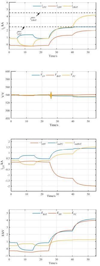
5
battery to be supplied by the fuel cell and the HV bus. The input current goes negative, while the other two input currents increase to satisfy the new amount of power requested at LV bus (Fig. 3a). The power sharing ratio between the fuel cell and the HV bus is kept at 1 : 3 with, −iLHV ≈ 250A and ioutF C ≈ 750A, as shown in Fig. 3c. The LV voltage remains closely regulated to the desired 540V value. After 10s the set value of the power return to its initial 0 value, allowing the battery to return to its former discharing state. The power sharing ratio comes back to 3 : 2 : 1 as displayed in Fig.3c.
At t = 25s the set value of the power of the HV bus becomes negative PsetHV = −950kW and, thus, power is needed from the battery and the fuel cell to be injected in the HV bus. After a short transient, the LV bus voltage drops down to 537V according to Fig. 3b. The input current becomes positive and, therefore, starts flowing towards the HV bus (Fig. 3a) while the power sharing between the battery and fuel cell is kept close the desired proportion of 3 : 2 having ioutF C ≈ 1.33kA and ioutBAT ≈ 0.89kA, as presented in Fig. 3c given the fact that none of the inductor currents have reached their maximum allowed current.
To test the overcurrent protection capability, the HV power demand is further increased. Thus, at t = 40s the set value of the power required by the HV bus goes even higher than before, PsetHV = −1.5MW , forcing the battery and the fuel cell to increase their power injection in the HV bus. As noticed
in Fig. 3a, the input current of the fuel cell reaches its limit iLF C = imaxLF C = 2.5kA, and the power sharing is sacrificed
(Fig. 3c) to ensure uninterruptible power supply to the LV and HV loads. The LV voltage remains within the desired range, VLV = 535V with a voltage drop of 5V , which is less than
1%.
Consequently, to further verify the theory presented, the controller state E is presented in Fig. 3d. When the input current of the fuel cell reaches its maximum, the virtual
voltage of the fuel cell also arrives at its imposed limit
EF C = EmaxF C = imaxLF C rvF C = 1.25kV .
VI. CONCLUSIONS
In this paper a detailed control design was presented for an on-board aircraft DC power distribution system. The nonlinear dynamic control scheme was developed to ensure power sharing and DC bus voltage regulation, with an inherent protection against overcurrents. By incorporating a constant virtual resistance and bounded virtual voltage dynamics, it has been proven that the input currents of the converters will never violate a maximum given value. This feature is guaranteed without any knowledge of the system parameters and without any extra measures such as limiters or saturators, thus, addressing integrator wind-up and instability problems that often happen with the traditional overcurrent controllers’ design. The effectiveness of the proposed scheme and its overcurrent capability was tested by simulating an on-board aircraft DC micro-grid under several scenarios. Future work will look into the integration of the HV side of the DC network and the AC/DC three-phase power converters.
(a) inductor currents
(b) LV bus voltages
(c) LV bus currents
(d) virtual voltages
Figure 3. Simulation results of the bidirectional DC/DC converter equipped with the proposed controller
REFERENCES
[1]J. A. Rosero, J. A. Ortega, E. Aldabas, and L. Romeral, “Moving towards a more electric aircraft,” IEEE Aerospace and Electronic Systems Magazine, vol. 22, no. 3, pp. 3–9, March 2007.
[2]E. Alcorta-Garcia, A. Zolghadri, and P. Goupil, “A nonlinear observerbased strategy for aircraft oscillatory failure detection: A380 case study,”
IEEE Transactions on Aerospace and Electronic Systems, vol. 47, no. 4, pp. 2792–2806, OCTOBER 2011.
[3]A. Ghodbane, M. Saad, C. Hobeika, J. â. Boland, and C. Thibeault, “Design of a tolerant flight control system in response to multiple actuator control signal faults induced by cosmic rays,” IEEE Transactions on Aerospace and Electronic Systems, vol. 52, no. 2, pp. 681–697, April 2016.
[4]H. Zhang, F. Mollet, C. Saudemont, and B. Robyns, “Experimental validation of energy storage system management strategies for a local dc distribution system of more electric aircraft,” IEEE Transactions on Industrial Electronics, vol. 57, no. 12, pp. 3905–3916, Dec 2010.
[5]F. Gao, S. Bozhko, G. Asher, P. Wheeler, and C. Patel, “An improved voltage compensation approach in a droop-controlled dc power system for the more electric aircraft,” IEEE Transactions on Power Electronics, vol. 31, no. 10, pp. 7369–7383, Oct 2016.
[6]P. Magne, B. Nahid-Mobarakeh, and S. Pierfederici, “Active stabilization of dc microgrids without remote sensors for more electric aircraft,” IEEE Transactions on Industry Applications, vol. 49, no. 5, pp. 2352–2360, Sept 2013.
[7]J.-H. Su, J.-J. Chen, and D.-S. Wu, “Learning feedback controller design of switching converters via matlab/simulink,” IEEE Transactions on Education, vol. 45, no. 4, pp. 307–315, 2002.
[8]G. Buticchi, L. Costa, and M. Liserre, “Improving system efficiency for the more electric aircraft: A look at dcdc converters for the avionic onboard dc microgrid,” IEEE Industrial Electronics Magazine, vol. 11, no. 3, pp. 26–36, Sept 2017.
[9]Z. Chen, W. Gao, J. Hu, and X. Ye, “Closed-loop analysis and cascade control of a nonminimum phase boost converter,” IEEE Trans. Power Electron., vol. 26, no. 4, pp. 1237–1252, 2011.
[10]S. Singh, D. Fulwani, and V. Kumar, “Robust sliding-mode control of dc/dc boost converter feeding a constant power load,” IET Power Electronics, vol. 8, no. 7, pp. 1230–1237, 2015.
[11]R. Sira-Ramirez, H.and Silva-Ortigoza, Control Design Techniques in Power Electronics Devices. Springer, London, 2006.
[12]Y. I. Son and I. H. Kim, “Complementary PID controller to passivitybased nonlinear control of boost converters with inductor resistance,”
IEEE Trans. Control Syst. Technol., vol. 20, no. 3, pp. 826–834, May 2012.
[13]H. Zhang, C. Saudemont, B. Robyns, and M. Petit, “Comparison of technical features between a more electric aircraft and a hybrid electric vehicle,” in 2008 IEEE Vehicle Power and Propulsion Conference, Sept 2008, pp. 1–6.
[14]D. Barater, F. Immovilli, A. Soldati, G. Buticchi, G. Franceschini, C. Gerada, and M. Galea, “Multistress characterization of fault mechanisms in aerospace electric actuators,” IEEE Transactions on Industry Applications, vol. 53, no. 2, pp. 1106–1115, March 2017.
[15]S. Pugliese, R. A. Mastromauro, and S. Stasi, “270v/28v wide bandgap device-based dab converter for more-electric-aircrafts: Feasibility and optimization,” in 2016 International Conference on Electrical Systems for Aircraft, Railway, Ship Propulsion and Road Vehicles International Transportation Electrification Conference (ESARS-ITEC), Nov 2016, pp. 1–6.
[16]M. Tariq, A. I. Maswood, C. J. Gajanayake, and A. K. Gupta, “Aircraft batteries: current trend towards more electric aircraft,” IET Electrical Systems in Transportation, vol. 7, no. 2, pp. 93–103, 2017.
[17]B. Karanayil, M. Ciobotaru, and V. G. Agelidis, “Power flow management of isolated multiport converter for more electric aircraft,” IEEE Transactions on Power Electronics, vol. 32, no. 7, pp. 5850–5861, July 2017.
[18]G. C. Konstantopoulos and Q.-C. Zhong, “Current-limiting non-linear controller for single-phase AC/DC PWM power converters,” in 2015 American Control Conference (ACC), Chicago, IL, July 1-3 2015, pp. 1029–1034.
[19]Q.-C. Zhong and G. C. Konstantopoulos, “Nonlinear current-limiting control for grid-tied inverters,” in 2016 American Control Conference (ACC), Boston, MA, USA, 6-8 July 2016, pp. 7472–7477.
[20]Y. Xue and J. M. Guerrero, “Smart inverters for utility and industry applications,” in Proceedings of PCIM Europe 2015; International Exhibition and Conference for Power Electronics, Intelligent Motion, Renewable Energy and Energy Management, May 2015, pp. 1–8.
6
[21]M. Mahmoodi, G. B. Gharehpetian, M. Abedi, and R. Noroozian, “A suitable control strategy for source converters and a novel loadgeneration voltage control scheme for dc voltage determination in dc distribution systems,” in 2006 IEEE International Power and Energy Conference, Nov 2006, pp. 363–367.
[22]H. Khalil, Nonlinear Systems, ser. Pearson Education. Prentice Hall, 2002.
[23]R. Ortega, A. Loria, P. J. Nicklasson, and H. Sira-Ramirez, Passivitybased Control of Euler-Lagrange Systems, Mechanical, Electrical and Electromechanical Applications. Springer-Verlag. Great Britain, 1998.
[24]P. Karlsson and J. Svensson, “Dc bus voltage control for a distributed power system,” IEEE Transactions on Power Electronics, vol. 18, no. 6, pp. 1405–1412, Nov 2003.
[25]J. Schonbergerschonberger, R. Duke, and S. D. Round, “Dc-bus signaling: A distributed control strategy for a hybrid renewable nanogrid,”
IEEE Transactions on Industrial Electronics, vol. 53, no. 5, pp. 1453– 1460, Oct 2006.
[26]P. H. Huang, P. C. Liu, W. Xiao, and M. S. E. Moursi, “A novel droopbased average voltage sharing control strategy for dc microgrids,” IEEE Transactions on Smart Grid, vol. 6, no. 3, pp. 1096–1106, May 2015.
[27]Z. Shuai, D. He, J. Fang, Z. J. Shen, C. Tu, and J. Wang, “Robust droop control of dc distribution networks,” IET Renewable Power Generation, vol. 10, no. 6, pp. 807–814, 2016.
[28]Q. C. Zhong, “Robust droop controller for accurate proportional load sharing among inverters operated in parallel,” IEEE Transactions on Industrial Electronics, vol. 60, no. 4, pp. 1281–1290, April 2013.