

Лабораторная работа №1,2 / FM_SPAJ141C_EN_BBA
.pdfNOTE! During any local man-machine communication over the push buttons and the display on the front panel a five minute time-out function is active. Thus, if no push button has been pressed during the last five minutes, the relay returns to its normal state automatically. This means that the display turns dark, the relay escapes from a display mode, a programming routine or any routine going on, when the relay is left untouched. This is a convenient way out of any situation when the user does not know what to do.
Before a relay module is inserted into the relay case, one must assure that the module has been given the correct settings. If there however is
any doubt about the settings of the module to be inserted, the setting values should be read using a spare relay unit or with the relay trip circuits disconnected. If this cannot be done the relay can be sett into a non-tripping mode by pressing the PROGRAM push button and powering up the relay module simultaneously. The display will show three dashes "- - -" to indicate the nontripping mode. The serial communication is operative and all main and submenues are accessible. In the non-tripping mode unnecessary trippings are avoided and the settings can be checked. The normal protection relay mode is entered automatically after a timeout of five minutes or ten seconds after the dark display position of the main menu has been entered.
|
MAIN MENU |
|
|
SUBMENU |
|
SETTING MODE |
|
REV. STEP 0,5 s |
|
|
|
|
|
||
|
|
STEP 0,5 s |
PROGRAM 1 s |
PROGRAM 5 s |
PROGRAM 5 s |
||
FWD.STEP 1 s |
|
|
|
|
|
||
Normal status, display off |
|
|
|
|
|
|
|
First measuring value |
|
|
|
|
|
|
|
|
|
REV. STEP 0,5 s |
|
|
|
|
|
|
|
|
|
|
|
INCREASE VALUE |
|
Last measuring value |
|
|
|
|
|
STEP 0,5 s |
|
|
FWD.STEP 1 s |
|
|
|
|
||
|
|
|
|
|
|
||
Actual setting value 1 |
1 |
Main setting |
1 |
0 |
0 |
0 |
|
value for stage 1 |
|||||||
|
|
|
|
|
|
||
Actual setting value 2 |
2 |
Second setting |
MOVE FIGURE OR DECIMAL POINT |
||||
value for stage 1 |
|||||||
|
|
|
CURSOR WITH BUTTON PROGRAM 1 s |
||||
|
|
|
STORE NEW SETTING BY PRESSING |
||||
Memorized values etc. |
|
|
STEP AND PROGRAM SIMULTANEOUSLY |
||||
|
|
|
WHEN THE VALUE IS READY AND THE |
||||
|
|
|
WHOLE DISPLAY IS BLINKING |
||||
NOTE! IN MOST MENU CHARTS THE SUBMENUS HAVE BEEN DRAWN IN A HORIZONTAL DIRECTION IN ORDER TO GET |
|||||||
ALL MAIN AND SUBMENU POSITIONS SHOWN IN THE SAME CHART. |
|
|
|
|
|||
Fig.3. Basic principles of entering the main menus and submenus of a relay module.
5

MAIN MENU |
|
SUBMENUS |
R
E
V.
S
T
E
P
.5 s
M
A
I
N
M
E
N
U
F
W
D.
S
T
E
P
1 s
STEP 0.5 s |
|
PROGRAM 1 s |
|
|
|
Normal status, display off
Current on phase L1
Current on phase L2
|
Current on phase L3 |
|
|
|
|
|
Neutral current Io |
|
REV. STEP 0.5 s |
SUBMENUS |
FWD. STEP 1 s |
|
|
|
|
||
|
|
|
|
|
|
|
Actual start value I> |
1 |
Main setting |
2 |
Second setting |
|
value for I> |
value for I> |
|||
|
|
|
|||
|
Actual operate time t> or |
1 |
Main setting |
2 |
Second setting |
|
multiplier k for stage I> |
value for t> or k |
value for t> or k |
||
|
|
|
|||
|
Actual start value I>> |
1 |
Main setting |
2 |
Second setting |
|
value for I>> |
value for I>> |
|||
|
|
|
|
||
|
Actual operate time t>> |
1 |
Main setting |
2 |
Second setting |
|
of stage I>> |
value for t>> |
value for t>> |
||
|
|
|
|||
|
Actual start value Io> |
1 |
Main setting |
2 |
Second setting |
|
value for Io> |
value for Io> |
|||
|
|
|
|
||
|
Actual operate time to> |
1 |
Main setting |
2 |
Second setting |
|
or multiplier ko |
value for to> or ko |
value for to> or ko |
||
|
|
|
|||
|
Actual start value Io>> |
1 |
Main setting |
2 |
Second setting |
|
value for Io>> |
value for Io>> |
|||
|
|
|
|
||
|
Actual operate time to>> |
1 |
Main setting |
2 |
Second setting |
|
value for to>> |
value for to>> |
|||
|
|
|
|
||
|
Actual setting of functional |
1 |
Main setting of |
2 |
Main setting of |
|
switchgroup SGF1 |
|
SGF1 checksum |
|
SGF2 checksum |
|
Actual setting of blocking |
1 |
Main setting of |
2 |
Second setting of |
|
switchgroup SGB |
|
SGB checksum |
|
SGB checksum |
|
Actual setting of relay |
1 |
Main setting of |
2 |
Main setting of |
|
switchgroup SGR1 |
SGR1 checksum |
SGR2 checksum |
||
|
|
|
|||
1 |
Latest memorized, event (n) |
1 |
Event (n-1) |
2 |
Event (n-2) |
|
value of phase L1 |
|
value of phase L1 |
|
value of phase L1 |
2 |
Latest memorized, event (n) |
1 |
Event (n-1) |
2 |
Event (n-2) |
|
value of phase L2 |
|
value of phase L2 |
|
value of phase L2 |
3 |
Latest memorized, event (n) |
1 |
Event (n-1) |
2 |
Event (n-2) |
|
value of phase L3 |
|
value of phase L3 |
|
value of phase L3 |
4 |
Maximum demand current |
1 |
Highest maximum |
|
|
|
value for 15 minutes |
|
demand value found |
|
|
Fig. 4.Example of part of the main and submenus for the settings of the overcurrent and earth-fault relay module SPCJ 4D29. The settings currently in use are in the main manu and they are displayed by pressing the STEP push button. The main menu also includes the measured current values, the registers 1...9, 0 and A. The main and second setting values are located in the submenus and are called up on the display with the PROGRAM push button.
6

Example 1 |
Operation in the setting mode. Manual setting |
|
of the main setting of the start current value I> |
|
of an overcurrent relay module. The initial value |
for the main setting is 0.80 x In and for the second setting 1.00 x In. The desired main start value is 1.05 x In.
a)
Press push button STEP repeatedly until the LED close to the I> symbol is lit and the current start value appears on the display.
b)
Enter the submenu to get the main setting value by pressing the PROGRAM push button more than one second and then releasing it. The red display digit now shows a flashing number 1, indicating the first submenu position and the green digits show the set value.
c)
Enter the setting mode by pressing the PROGRAM push button for five seconds until the display starts flashing.
d)
Press the PROGRAM push button once again for one second to get the rightmost digit flashing.
e)
Now the flashing digit can be altered. Use the STEP push button to set the digit to the desired value.
f)
Press the PROGRAM push button to make the middle one of the green digits flash.
g)
Set the middle digit with of the STEP push button.
h)
Press the PROGRAM push button to make the leftmost green digit flash.
RESET
STEP
5 x 1 s
PROGRAM
1 s
PROGRAM
5 s
PROGRAM
1 s
RESET
STEP
5 x
PROGRAM
1 s
RESET
STEP
2 x
PROGRAM
1 s
 0. 8 0
 1
1 
 0. 8 0
 1
1 
 0.
0. 8
8 0
0

 1
1 
 0. 8
0. 8  0
0

 1
1
 0. 8
0. 8  5
5

 1
1 
 0.
0. 8
8
 5
5
 1
1 
 0.
0. 0
0
 5
5
 1
1 
 0. 0 5
7

i)
Set the digit with the STEP push button.
j)
Press the PROGRAM push button to make the decimal point flash.
k)
If needed, move the decimal point with the STEP push button.
l)
Press the PROGRAM push button to make the whole display flash. In this position, corresponding to position c) above, one can see the new value before it is recorded. If the value needs changing, use the PROGRAM push button to alter the value.
m)
When the new value has been corrected, record it in the memory of the relay module by pressing the PROGRAM and STEP push buttons simultaneously. At the moment the information enters the memory, the green dashes flash once in the display, i.e. 1 - - -.
n)
Recording of the new value automatically initiates a return from the setting mode to the normal submenu. Without recording one can leave the setting mode any time by pressing the PROGRAM push button for about five seconds, until the green display digits stop flashing.
RESET
STEP
0 x
PROGRAM
1 s
RESET
STEP
0 x
PROGRAM
1 s
RESET
STEP
PROGRAM
PROGRAM
5 s
 1
1
 1. 0 5
 1
1
 1.
1.
 0 5
0 5
 1
1
 1.
1.
 0 5
0 5
 1
1
 1.
1. 0
0 5
5

 1
1
 - - -
- - -
 1
1
 1. 0 5
o)
If the second setting is to be altered, enter submenu position 2 of the setting I> by pressing the STEP push button for approx. one second. The flashing position indicator 1 will then be replaced by a flashing number 2 which indicates that the setting shown on the display is the second setting for I>.
Enter the setting mode as in step c) and proceed in the same way. After recording of the requested values return to the main menu is obtained by pressing the STEP push button
RESET |
|
STEP |
2 1. 0 0 |
1 s |
until the first digit is switched off. The LED still shows that one is in the I> position and the display shows the new setting value currently in use by the relay module.
8

Example 2 |
Operation in the setting mode. Manual setting |
|
of the main setting of the checksum for the |
|
switchgroup SGF1 of a relay module. The initial |
|
value for the checksum is 000 and the switches |
SGF1/1and SGF1/3 are to be set in position 1. This means that a checksum of 005 should be the final result.
a)
Press push button STEP until the LED close to the SGF symbol is lit and the checksum appears on the display.
b)
Enter the submenu to get the main checksum of SGF1 by pressing the PROGRAM push button for more than one second and then releasing it. The red display now shows a flashing number 1 indicating the first submenu position and the green digits show the checksum.
RESET
STEP
n x 1 s
PROGRAM
1 s
 0 0 0
0 0 0
 1
1 
 0 0 0
0 0 0
c)
Enter the setting mode by pressing the PROGRAM push button for five seconds until the display starts flashing.
d)
Press the PROGRAM push button once again to get the first switch position. The first digit of the display now shows the switch number. The position of the switch is shown by the rightmost digit.
e)
The switch position can now be toggled between 1 and 0 by means of the STEP push button and it is left in the requested position 1.
f)
When switch number 1 is in the requested position, switch number 2 is called up by pressing the PROGRAM push button for one second. As in step e), the switch position can be altered by using the STEP push button. As the desired setting for SGF1/2 is 0 the switch is left in the 0 position.
g)
Switch SGF1/3 is called up as in step f) by pressing the PROGRAM push button for about one second.
PROGRAM
5 s |
0 |
0 0 |
1 |
PROGRAM
1 x
|
|
|
|
|
|
|
|
|
|
|
|
1 |
|
1 |
|
|
|
0 |
|
||
|
|
|
|
|
|
|||||
|
|
|
|
|
|
|
|
|
|
|
RESET |
|
|
|
|
STEP |
1 |
1 |
1 |
|
1 x |
||||
|
|
|
PROGRAM |
1 2 |
0 |
1 s |
1 s |
1 3 |
0 |
PROGRAM |
|
|
9

h)
The switch position is altered to the desired position 1 by pressing the STEP push button once.
i)
Using the same procedure the switches SGF 1/ 4...8 are called up and, according to the example, left in position 0.
j)
In the final setting mode position, corresponding to step c), the checksum based on the set switch positions is shown.
k)
If the correct checksum has been obtained, it is recorded in the memory by pressing the push buttons PROGRAM and STEP simultaneously. At the moment the information enters the memory, the green dashes flash in the display, i.e.1 - - -. If the checksum is incorrect, the setting of the separate switches is repeated using the PROGRAM and STEP push buttons starting from step d).
RESET |
|
|
|
STEP |
1 |
3 |
1 |
1 x |
|||
|
PROGRAM
5 x 1 s
 1
1
 0
0
 0
0 5
5

RESET
STEP
 1
1
 - - -
- - -
PROGRAM
l)
Recording the new value automatically initiates a return from the setting mode to the normal menu. Without recording one can leave the setting mode any time by pressing the PROGRAM push button for about five seconds, until the green display digits stop flashing.
PROGRAM 5 s |
1 |
0 |
0 5 |
|
m)
After recording the desired values return to the main menu is obtained by pressing the STEP push button until the first digit is turned off. The LED indicator SGF still shows that one is in the SGF position and that the display shows the new checksum for SGF1 currently in use by the relay module.
RESET STEP
n x 1 s  0 0 5
0 0 5
10
Recorded information
The parameter values measured at the moment when a fault occurs or at the trip instant are recorded in the registers. The recorded data, except for some parameters, are set to zero by pressing the push buttons STEP and PROGRAM simultaneously. The data in normal registers are erased if the auxiliary voltage supply to the relay is interrupted, only the set values and certain other essential parameters are maintained in non-volatile registers during a voltage failure.
The number of registers varies with different relay module types. The functions of the registers are illustrated in the descriptions of the different relay modules. Additionally, the system front panel of the relay contains a simplified list of the data recorded by the various relay modules of the protection relay.
All D type relay modules are provided with two general registers: register 0 and register A.
Register 0 contains, in coded form, the information about e.g. external blocking signals, status information and other signals. The codes are explained in the manuals of the different relay modules.
Register A contains the address code of the relay modul which is reqiured by the serial communication system.
Submenu 1 of register A contains the data transfer rate value, expressed in kilobaud, of the serial communication.
Submenu 2 of register A contains a bus communication monitor for the SPAbus. If the protection relay, which contains the relay module, is linked to a system including a contol data communicatoe, for instance SRIO 1000M and the data communication system is operating, the counter reading of the monitor will be zero. Otherwise the digits 1...255 are continuously scrolling in the monitor.
Submenu 3 contains the password required for changing the remote settings. The address code, the data transfer rate of the serial communication and the password can be set manually or via the serial communication bus. For manual setting see example 1.
The default value is 001 for the address code, 9.6 kilobaud for the data transfer rate and 001 for the password.
In order to secure the setting values, all settings are recorded in two separate memory banks within the non-volatile memory. Each bank is complete with its own checksum test to verify the condition of the memory contents. If, for some reason, the contents of one bank is disturbed, all settings are taken from the other bank and the contents from here is transferred to the faulty memory region, all while the relay is in full operation condition. If both memory banks are simultaneously damaged the relay will be be set out of operation, and an alarm signal will be given over the serial port and the IRF output relay
11
Trip test function Register 0 also provides access to a trip test function, which allows the output signals of the relay module to be activated one by one. If the auxiliary relay module of the protection assembly is in place, the auxiliary relays then will operate one by one during the testing.
When pressing the PROGRAM push button for about five seconds, the green digits to the right start flashing indicating that the relay module is in the test position. The indicators of the settings indicate by flashing which output signal can be activated. The required output function is selected by pressing the PROGRAM push button for about one second.
The indicators of the setting quantities refer to the following output signals:
The selected starting or tripping is activated by simultaneous pressing of the push buttons STEP and PROGRAM. The signal remains activated as long as the two push butttons are pressed. The effect on the output relays depends on the configuration of the output relay matrix switches.
The self-supervision output is activated by pressing the STEP push button 1 second when no setting indicator is flashing. The IRF output is activated in about 1 second after pressing of the STEP push button.
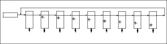
The signals are selected in the order illustrated in Fig. 4.
Setting |
I> |
Starting of stage |
I> |
Setting |
t> |
Tripping of stage |
I> |
Setting |
I>> |
Starting of stage |
I>> |
Setting |
t>> |
Tripping of stage I>> |
|
etc. |
|
|
|
No indication |
Self-supervision IRF |
||
IRF |
|
I> START |
|
I> TRIP |
|
I» START |
|
I» |
TRIP |
Io> START |
Io> TRIP |
Io»START |
Io» TRIP |
|
|
|
|
|
|||||||||
REGISTER 0 |
|
|
|
|
|
|
|
|
|
|
|
|
|
PROGRAM |
PROGRAM |
I> |
PROGRAM |
t> |
PROGRAM |
|
PROGRAM |
|
PROGRAM |
PROGRAM |
PROGRAM |
PROGRAM |
PROGRAM |
5 s |
1 s |
|
1 s |
1 s |
I» |
1 s |
|
1 s |
1 s |
1 s |
1 s |
1 s |
|
|
|
|
|
|
|
|
|
|
t» |
|
|
|
|
|
|
|
|
|
|
|
|
|
|
Io> |
to> |
|
|
|
|
|
|
|
|
|
|
|
|
|
|
Io» |
|
|
|
|
|
|
|
|
|
|
|
|
|
|
to» |
STEP |
|
STEP & |
|
STEP & |
|
STEP & |
|
STEP & |
STEP & |
STEP & |
STEP & |
STEP & |
|
|
|
PROGRAM |
|
PROGRAM |
|
PROGRAM |
|
PROGRAM |
PROGRAM |
PROGRAM |
PROGRAM |
PROGRAM |
|
Fig. 5.Sequence order for the selection of output signals in the Trip test mode
If, for instance, the indicator of the setting t> is flashing, and the push buttons STEP and PROGRAM are being pressed, the trip signal from the low-set overcurrent stage is activated. Return to the main menu is possible at any stage of the trip test sequence scheme, by pressing the PROGRAM push button for about five seconds.
Note!
The effect on the output relays then depends on the configuration of the output relay matrix switchgroups SGR 1...3.
12

Example 3 |
Trip test function. Forced activation of the |
||
|
outputs. |
||
|
a) |
||
|
Step forward on the display to register 0. |
||
|
|
|
|
|
|
RESET |
|
|
|
STEP |
n x 1 s |
|
|
|
|
b)
Press the PROGRAM push button for about five seconds until the three green digits to the right.
PROGRAM
5 s
c)
Hold down the STEP push button. After one second the red IRF indicator is lit and the IRF output is activated. When the step push button is released the IRF indicator is switched off and the IRF output resets.
|
|
3 I |
> |
|
|
I |
|
I L1 I |
L2 I L3 |
I o IRF |
|
I > /I n |
RESET |
|
|
STEP |
|
||
t > [s] |
|
|
|
k |
|
|
|
I >>/ I n |
|
|
|
t >>[s] |
|
|
|
I o>/ I n |
|
|
|
to >[s] |
|
|
|
ko |
|
|
|
I o >>/I n |
|
|
|
to >>[s] |
|
|
|
|
|
PROGRAM |
|
SGF |
|
|
|
SGB |
|
|
|
SGR |
|
|
|
|
|
TRIP |
|
879B |
SPCJ 4D29 |
||
|
|
|
|
d)
Press the PROGRAM push button for one second and the indicator of the topmost setting start flashing.
e)
If a start of the first stage is required, now press the push-buttons PROGRAM and STEP simultaneously. The stage output will be activated and the output relays will operate according to the actual programming of the relay output switchgroups SGR.
RESET
STEP
|
|
3 I |
> |
|
|
I |
|
I L1 I |
L2 I L3 |
I o IRF |
|
I > /I n |
RESET |
|
|
STEP |
|
||
t > [s] |
|
|
|
k |
|
|
|
I >>/ I n |
|
|
|
t >>[s] |
|
|
|
I o>/ I n |
|
|
|
to >[s] |
|
|
|
ko |
|
|
|
I o >>/I n |
|
|
|
to >>[s] |
|
|
|
|
|
PROGRAM |
|
SGF |
|
|
|
SGB |
|
|
|
SGR |
|
|
|
|
|
TRIP |
|
879B |
SPCJ 4D29 |
||
|
|
|
|
PROGRAM
0 0 0 0
0  0
0
 0
0 0
0

0  0
0
 0
0 0
0

13

f)
To proceed to the next position press the PROGRAM push button for about 1 second until the indicator of the second setting starts flashing.
PROGRAM 1 s
g)
Press the push buttons PROGRAM and STEP simultaneously to activate tripping of stage 1 (e.g. the I> stage of the overcurrent module SPCJ 4D29). The output relays will operate according to the actual programming of the relay switchgroups SGR. If the main trip relay is operated the trip indicator of the measuring module is lit.
RESET
STEP
PROGRAM
|
|
3 I |
> |
|
|
I |
|
I L1 I |
L2 I L3 |
I o IRF |
|
I > /I n |
RESET |
|
|
STEP |
|
||
t > [s] |
|
|
|
k |
|
|
|
I >>/ I n |
|
|
|
t >>[s] |
|
|
|
I o>/ I n |
|
|
|
to >[s] |
|
|
|
ko |
|
|
|
I o >>/I n |
|
|
|
to >>[s] |
|
|
|
|
|
PROGRAM |
|
SGF |
|
|
|
SGB |
|
|
|
SGR |
|
|
|
|
|
TRIP |
|
879B |
SPCJ 4D29 |
||
|
|
|
|
|
|
3 I |
> |
|
|
I |
|
I L1 I |
L2 I L3 |
I o IRF |
|
I > /I n |
RESET |
|
|
STEP |
|
||
t > [s] |
|
|
|
k |
|
|
|
I >>/ I n |
|
|
|
t >>[s] |
|
|
|
I o>/ I n |
|
|
|
to >[s] |
|
|
|
ko |
|
|
|
I o >>/I n |
|
|
|
to >>[s] |
|
|
|
|
|
PROGRAM |
|
SGF |
|
|
|
SGB |
|
|
|
SGR |
|
|
|
|
|
TRIP |
|
879B |
SPCJ 4D29 |
||
|
|
|
|
0  0
0
 0
0  0
0

0  0
0
 0
0 0
0

h)
The starting and tripping of the remaining stages are activated in the same way as the first stage above. The indicator of the corresponding setting starts flashing to indicate that the concerned stage can be activated by pressing the STEP and PROGRAM buttons simultaneously. For any forced stage operation, the output relays will respond according to the setting of the relay output switchgroups SGR. Any time a certain stage is selected that is not wanted to operate, pressing the PROGRAM button once more will pass by this position and move to the next one without carrying out any operation of the selected stage.
It is possible to leave the trip test mode at any step of the sequence scheme by pressing the PROGRAM push button for about five seconds until the three digits to the right stop flashing.
14