

Лабораторная работа №1,2 / FM_SPAJ141C_EN_BBA
.pdfSPAJ 141 C
Overcurrent and earth-fault relay
User´s manual and Technical description
0084A
2
I n = |
1A |
5A (I ) |
|
5 |
|
I n = |
0.2A |
1A (I o) |
fn = 50 / 60 Hz |
||
|
SPAJ 141 C
|
80...265V |
|
– |
|
|
|
|
|
|
|
|
|
||||||
|
|
|
|
|
|
|
|
|
|
|||||||||
|
|
|
|
|
|
|
|
~ |
|
|
|
|
U aux |
|||||
|
18...80V – |
|
|
|
|
|||||||||||||
|
|
|
|
|
|
|
|
|
SPCJ 4D24 |
|
|
|
|
|
|
|||
REGISTERS |
|
|
|
OPER.IND. |
||||||||||||||
|
|
|
|
|
|
|
|
|
|
|
|
|
|
|
|
|
|
|
0 |
|
0 |
|
|
0 |
0 |
|
|
|
0 |
|
|
|
|
|
|
|
|
|
|
|
|
|
|
|
|
|
|
|
|
|
|
|
||||
1 |
|
I L1 /I n |
|
|
|
|
1 |
|
I >START |
|||||||||
2 |
|
I L2 /I n |
|
|
|
|
2 |
|
I >TRIP |
|||||||||
3 |
|
I L3 /I n |
|
|
|
|
3 |
|
I >>START |
|||||||||
4 |
|
I max (15min) /I n |
4 |
|
I >>TRIP |
|||||||||||||
5 |
|
t (I |
> [ |
% |
] |
|
|
5 |
|
> |
|
|
|
|
||||
|
|
|
) |
|
|
|
|
I o START |
||||||||||
6 |
|
t (I |
>> [ |
% |
] |
|
|
6 |
|
> |
|
|
|
|
||||
|
|
|
) |
|
|
|
|
I o TRIP |
||||||||||
7 |
|
I o [ % I n ] |
|
|
7 |
|
I o>>START |
|||||||||||
8 |
|
t (I o >)[ % ] |
8 |
|
I o>>TRIP |
|||||||||||||
9 |
|
t (I o |
>> [ |
% |
] |
9 |
|
CBFP |
||||||||||
|
) |
|
|
|
||||||||||||||
RS 611 |
|
|
|
|
|
Ser.No. |
|
|
|
|
|
|
||||||
0085A
3 I >
I 
 I L1 I L2 I L3 I o IRF
I > /I n |
RESET |
STEP |
t > [s] k
 I >>/ I n
 t >>[s]
 I o > [ %I n ]
 to >[s]
 I o >> [ %I n ]
 to >>[s]
PROGRAM
 SGF
SGF
 SGB
SGB
 SGR
SGR
TRIP
SPCJ 4D24

1MRS 750872-MUM EN
Issued 1997-10-13
Modified 2002-04-22
Version B (replaces 34 SPAJ 17 EN1)
Checked MK
Approved OL
Data subject to change without notice
SPAJ 141 C
Combined overcurrent and earth-fault relay
Contents |
Characteristics ................................................................................................................ |
2 |
|
Application ..................................................................................................................... |
2 |
|
Description of operation ................................................................................................. |
3 |
|
Connection diagram ....................................................................................................... |
4 |
|
Connections ................................................................................................................... |
6 |
|
Control signals between the modules .............................................................................. |
7 |
|
Signal abbreviations used ................................................................................................ |
7 |
|
Operation indicators ....................................................................................................... |
8 |
|
Power supply and output relay module ........................................................................... |
9 |
|
Technical data (modified 2002-04) ................................................................................ |
10 |
|
Maintenance and repairs ............................................................................................... |
13 |
|
Spare parts .................................................................................................................... |
13 |
|
Dimensions and instructions for mounting .................................................................. |
14 |
|
Ordering information ................................................................................................... |
15 |
|
The complete manual for the relay SPAJ 141 C contains the following partial manuals: |
|
General relay description
General characteristics of D-type relay modules Combined overcurrent and earth-fault module SPCJ 4D24
1MRS 750872-MUM EN 1MRS 750066-MUM EN 1MRS 750121-MUM EN
Characteristics Three-phase low-set overcurrent unit with definite time or inverse definite minimum time (IDMT) characteristic.
Three-phase high-set overcurrent unit with instantaneous or definite time function.
Low-set sensitive, non-directional earth-fault protection with definite time characteristic.
High-set non-directional earth-fault protection with instantaneous or definite time function.
Built-in breaker failure protection scheme.
Fully field-selectable output relay configuration.
Extensive data communication capabilities over built-in serial port.
Outstanding design flexibility for easy selection of appropriate operation schemes for various applications.
Numerical display of setting values, current measured values, memorized fault values etc.
Continuous self-supervision with auto-diagno- sis of internal faults.
Application |
The combined overcurrent and earth-fault relay |
|
SPAJ 141 C is intended to be used for the selec- |
|
tive short-circuit and earth-fault protection of |
|
radial feeders in resistance earthed or impedance |
|
earthed power systems. The integrated protec- |
|
tive relay comprises both an overcurrent unit and |
|
an earth-fault unit with highly flexible tripping |
and signalling facilities.The feeder protection can be used in applications requiring a single-, twoor three-phase overcurrent protection and a nondirectional earth-fault protection. The overcurrent and earth-fault relay also comprises a circuit breaker failure protection.
2

Description of operation
The combined overcurrent and earth-fault relay is a secondary relay device to be connected to the current transformers of the feeder to be protected. The three-phase overcurrent unit and the non-directional earth-fault unit continuously measure the phase currents and the neutral current of the protected feeder. In fault situations these units initiate external auto-reclose functions or trip the circuit-breaker, depending on the selected protective scheme.
When a phase current exceeds the starting value of the low-set overcurrent unit, the unit starts, simultaneously starting the corresponding timing circuit. When the set operating time has elapsed, a circuit-breaker tripping command is delivered. Correspondingly, the high-set stage of the overcurrent unit starts when its starting value is exceeded, starting its timing circuit and performing a tripping when the set time has elapsed.
The low-set stage of the non-directional earthfault unit operates in the same way. Depending on the protective scheme it either signals, performs a tripping or initiates a function of an external auto-reclose relay. The input circuit comprises a low-pass filter, which reduces the amount of harmonics in the neutral current before the signal is measured.
The low-set stage of the overcurrent unit may be given definite time or inverse definite minimum time (IDMT) characteristics. When the IDMT characteristic is to be chosen six curve types are available in the relay. Four of the curves types comply with BS 142 and IEC 60255 and are named normal inverse, very inverse, extremely inverse and long-time inverse.The two additional curves are named the RI curve and the RXIDG curve. The low-set stage of the earth-fault unit is operating on a definite time basis.
By appropriate programming of the tripping relay matrix, the starting signals of the overcurrent and non-directional earth-fault modules are received as contact functions. This contact information is used e.g. for the blocking of cooperating protective relays located upstreams.
The relay comprises one external logic control input, which is actuated by a control signal of the auxiliary voltage level. The influence on the relay by the control input is determined by programming switches in the measuring module. The control input can be used either for blocking one or more of the protective stages, for resetting a latched output relay in the manual reset mode or for selecting a new group of relay settings by remote control.
|
|
|
|
|
|
|
Trip |
|
|
|
|
|
|
|
|
|
|
|
|
|
|
Three phase definite time or |
|
|
|
|
|
|
|
|
51 |
|
|
|
|
|
|
|
|
dependent time low-set |
|
|
|
|
|
IL1 |
|
overcurrent protection |
|
|
|
|
|
|
|
|
|
|
|
|
|
|
|
|
|
|
|
|
|
|
|
|
|
|
|
|
|
|
|
|
|
|
|
|
Three phase instantaneous or |
|
|
Signal 1 |
|
|
|
|
|
dependent time high-set |
50 |
|
|
|
|
|
|
|
overcurrent protection |
|
|
|
|
|
IL2 |
|
|
|
|
|
|
|
|
|
|
|
|
|
|
||
|
|
|
|
|
|
|
|
|
|
|
|
|
Definite time low-set |
51 N |
|
Signal 2 |
|
|
|
|
|
earth-fault protection |
|
|
||
|
|
|
|
|
|
|
||
|
IL3 |
|
|
|
|
|
|
|
|
|
|
|
|
|
|
||
|
|
|
|
|
|
|
||
|
|
|
|
Instantaneous or definite time |
50 N |
|
|
|
|
|
|
|
|
|
|
||
|
|
|
|
high-set earth-fault protection |
|
Start 1 |
|
|
|
|
|
|
|
|
|
||
|
|
|
|
|
|
|
|
|
|
|
|
|
|
|
|
|
|
|
|
|
|
|
|
|
|
|
|
Io |
|
Remote reset, remote setting control or |
|
|
Start 2 |
|
|
|
|
blocking input for the different current stages |
|
|
||||
|
|
|
|
|
|
|||
|
|
|
|
|
|
|
IRF |
|
|
|
|
|
|
|
|||
|
Blocking or |
|
Circuit breaker failure protection |
51BF |
|
|
||
|
reset |
|
|
|
|
Serial I/O |
|
|
|
|
|
|
|
|
|
|
|
|
|
|
|
|
|
|
|
|
|
|
|
|
|
|
|
|
|
|
|
|
|
|
|
|
|
|
|
|
|
|
Serial communication port |
|
|
|
|
|
|
|
|
|
|
|
||
|
|
|
|
|
|
|
|
|
|
|
|
|
|
|
|
|
|
|
|
|
|
|
|
|
|
|
Fig. 1. Protective functions of the overcurrent and earth-fault relay SPAJ 141 C.
3
Connection |
|
|
|
|
|
|
|
|
|
|
|
|
|
|
|
|
|
diagram |
|
|
|
|
|
|
|
|
|
|
|
|
|
|
|
|
|
SPAJ |
|
|
|
|
|
U3 |
|
|
1 63 |
|
|
|
|
|
|
|
|
141 |
|
|
|
|
|
|
|
|
5 A |
43 2 |
|
|
|
|
|
|
|
|
|
|
|
|
|
|
|
1 A |
|
|
|
|
|
|
|
||
C |
|
|
|
|
|
|
|
|
5 A |
6 5 |
|
|
|
|
|
|
|
|
|
|
|
|
|
|
|
1 A |
|
|
|
|
|
|
|
||
|
|
|
|
|
|
|
|
|
|
7 |
|
|
|
|
|
|
|
|
|
|
|
|
|
|
|
|
5 A |
8 |
|
|
|
|
|
|
|
|
|
|
|
|
|
|
|
|
1 A |
9 |
|
|
|
|
|
|
|
|
|
|
|
|
|
|
|
|
1 A |
27 25 |
|
|
|
|
|
|
|
|
|
|
|
|
|
|
|
|
0.2 A |
28 |
|
|
|
|
|
|
|
|
|
|
|
|
|
|
|
|
|
|
|
|
|
|
|
|
|
SGB/8 |
SGB/5 |
SGB/4 |
SGB/3 |
SGB/2 |
SGB/1 |
|
|
U2 |
|
10 11 |
|
EXTERNAL CONTROL |
|
|
|
|
|
RESET |
|
Io>> |
|
3I>> |
IRF U1 3I> |
|
|
+ |
~ |
62 |
|
|
|
|
|
|
|
I/O |
Io> |
|
|
F - |
7271 70 61 |
|
IRF |
(~)- |
(~)+ |
|
|
|
|||||
|
SETTINGSRC |
|
|
|
|
|
|
|
|
|
|
|
|
|
|
|
|
|
|
|
|
|
|
|
|
|
+ |
|
|
|
U |
|
|
|
|
|
|
|
|
|
|
|
|
|
|
|
|
|
L3 |
L2 |
L1 |
||
T9 |
|
|
|
|
SGR3/1 |
|
|
TS1 |
E |
7574 |
|
1START |
aux |
|
|||
|
|
|
|
SGR3/2 |
|
1 |
|
|
|||||||||
|
|
|
|
|
SGR3/3 |
|
|
|
|
|
|
|
|
|
|
|
|
|
|
|
|
|
SGR3/4 |
|
|
|
|
|
|
|
|
|
|
|
|
|
|
|
|
|
SGR3/5 |
|
|
|
|
|
|
|
|
|
|
|
|
|
|
|
|
|
SGR3/6 |
|
|
|
+ |
|
|
|
|
|
|
|
|
|
|
|
|
|
SGR3/7 |
|
|
|
|
|
|
|
|
|
|
|
|
|
|
|
|
|
SGR3/8 |
|
|
|
|
|
|
2START |
|
|
|
|
|
|
|
|
|
|
SGR1/1 |
|
1 |
SS1 |
D |
7877 |
|
|
|
|
|
|
|
|
|
|
|
|
|
|
|
|
|
|
|
|
|
|
|
|
|
|
|
|
|
|
SGR1/3 |
|
|
|
|
|
|
|
|
|
|
|
|
SGF/4 |
|
|
|
|
SGR1/5 |
|
|
|
+ |
|
|
|
|
|
|
|
|
|
|
|
|
SGR1/7 |
|
|
|
|
|
|
|
|
|
|
|
||
1s...1.0 |
|
T7 |
T5 |
T3 |
T1 |
|
|
SS2 |
C |
81 80 |
|
SIGNAL |
|
I |
|
|
|
|
|
|
|
|
SGR2/1 |
|
|
|
|
|
|
|
|
|
|
|
|
|
|
|
|
|
SGR2/3 |
|
|
|
|
|
|
|
|
|
|
|
|
|
|
|
|
|
SGR2/5 |
|
1 |
|
+ |
|
|
1 |
|
|
|
|
|
|
|
|
|
|
SGR2/7 |
|
|
|
|
|
|
|
|
|
|
|
|
|
|
|
|
|
|
|
|
|
|
|
|
|
|
|
|
|
|
|
|
|
|
|
|
|
|
|
|
|
|
SIGNAL |
|
+ |
|
|
|
|
|
|
|
|
SGR2/2 |
|
|
SS3 |
B |
6968 |
|
|
0 |
|
|
|
|
|
|
|
|
|
SGR2/4 |
|
|
|
|
|
|
|
|
|
|
|
|
|
|
|
|
|
SGR2/6 |
|
1 |
|
+ |
|
|
2 |
|
|
|
|
|
|
|
|
|
|
SGR2/8 |
|
|
|
|
|
|
|
|
|
|
|
|
|
|
|
|
|
|
|
|
|
|
|
|
|
+ |
|
|
|
|
|
|
|
|
|
|
|
|
|
|
|
|
|
|
|
|
|
|
|
|
|
|
|
SGB/7 |
SGB/6 |
LATCHING |
|
|
6665 |
|
TRIP |
|
- |
|
|
|
|
|
|
|
|
TS2 |
A |
|
+ |
I |
- |
|
|
|||||
|
|
|
|
|
|
|
|
|
|
|
|
|
|
|
0 |
|
|
|
|
|
|
|
SGR1/2 |
|
|
|
|
|
|
|
|
|
|
|
|
|
|
|
|
|
SGR1/4 |
|
|
|
|
|
|
|
|
|
|
|
|
|
|
|
|
|
SGR1/6 |
|
1 |
|
+ |
|
|
|
|
|
|
|
|
|
|
|
|
|
SGR1/8 |
|
|
|
|
|
|
|
|
|
|
|
|
|
|
|
|
|
|
|
|
|
|
|
|
|
|
|
|
|
|
|
|
|
|
|
|
|
R |
|
|
|
|
|
SPA-ZC_ |
|
|
|
|
|
|
|
|
|
|
|
|
|
|
|
|
|
|
|
|
|
|
U1 |
|
T8 |
T6 |
T4 |
T2 |
|
TRIP |
|
|
PORT |
SERIAL |
|
|
Tx Rx |
|
|
|
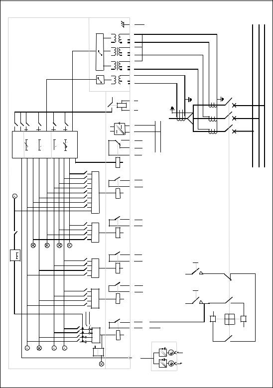
Fig. 2. Connection diagram for the combined overcurrent and earth-fault relay SPAJ 141 C with all the relay matrix switchgroups shown.
4
Uaux |
Auxiliary voltage |
A, B, C, D, E, F |
Output relays |
IRF |
Self-supervision |
SGR |
Switchgroups for the configuration of trippings and signallings |
SGB |
Switchgroup for the configuration of the blocking or control signal |
TRIP |
Trip output relay |
SIGNAL 1 |
Signal on overcurrent trip |
SIGNAL 2 |
Signal on earth-fault trip |
START 1 |
Starting or auxiliary trip signal as selected with switchgroup SGR3 |
START 2 |
Starting of overcurrent low-set stage I> |
U1 |
Three-phase overcurrent and non-directional earth-fault module SPCJ 4D24 |
U3 |
Input module SPTE 4E2 |
U2 |
Power supply and output relay module |
|
SPTU 240 R1 or SPTU 48 R1 |
T1…T8 |
Starting and tripping indications |
SERIAL PORT |
Serial communication interface |
SPA-ZC_ |
Bus connection module |
Rx/Tx |
Receiver bus terminal (Rx) and transmitter bus terminal (Tx) of the bus |
|
connection module |
Made in Finland
Serial Port |
SPA |
= 63
68
69
77
78
80
81
161
262
363
465
566
674
775
870
971
2572
2710
2811
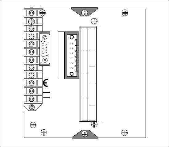
Fig. 3. Rear view of relay SPAJ 141 C.
5
Connections |
The three phase-currents of the overcurrent pro- |
|
tection are connected to terminals 1-2, 4-5 and |
|
7-8, when the rated current of the secondary |
|
circuits is In = 5 A. When using current trans- |
|
formers with a rated current of 1 A, terminals |
|
1-3, 4-6 and 7-9 are used. The overcurrent pro- |
|
tection may also be used in single-phase or two- |
|
phase applications, in which case inputs not to |
|
be used are left unconnected. In single-phase |
|
applications, however, wiring the phase current |
|
through two current inputs in series may in- |
|
crease the operating speed of the relay, particu- |
|
larly for instantaneous operations. |
|
The neutral current of the earth-fault protec- |
|
tion is connected to terminals 25-27 when the |
|
rated current is 1 A and to terminals 25-28 when |
|
the rated current is 0.2 A. |
|
The control input 10-11 can be used in three |
|
different ways, as the control input of an exter- |
|
nal blocking signal for the measuring modules, |
|
as the control input for unlatching the trip relay, |
|
or as the control input for the remote control |
|
of settings. The function is selected by means |
|
of switches 1...8 of switchgroup SGB in the |
|
main menu of the measuring relay module. |
|
The auxiliary supply voltage of the relay is con- |
|
nected to the terminals 61-62. At d.c. auxiliary |
|
supply voltage the positive lead is connected to |
|
terminal 61. The level of the voltage to be ap- |
|
plied to the terminals is determined by the type |
|
of power supply and output relay module in- |
|
serted in the protection. For further details see |
|
the description of the power supply module. The |
|
auxiliary voltage range of the relay has been |
|
marked on the front panel. |
|
Output relay A provides the CB tripping com- |
|
mands so that the CB operates once the operat- |
|
ing time of the low-set or high-set stage of the |
|
overcurrent or non-directional earth-fault mod- |
|
ule has elapsed. The stages to perform a trip- |
|
ping are selected with switches 2,4,6 and 8 of |
|
switchgroup SGR1. On delivery from factory |
|
all stages are selected to perform tripping. A |
|
latching function of the output relay A can be |
|
selected by means of switches SGB 6 and 7 for |
|
overcurrent and earth-fault trippings. |
|
The trip alarm signals from the measuring mod- |
|
ules are obtained through output relays B and |
|
C. The signals to be forwarded to the output |
|
relays B and C are selected with switches1...8 |
|
of switchgroup SGR2 of the measuring mod- |
|
ule. The switch matrixes for configuration of |
the control signals of the output relays B and C identical. Normally the output relays B and C are given such a configuration that low-set and high-set overcurrent trip alarm signal is obtained over relay C and the corresponding alarm signal for the earth-fault trips via output relay B. This is also the default setting on delivery.
The starting signals from the protective stages of the relay are received through output relay D. The signals to be forwarded to the output relay D are selected by means of switches 1, 3, 5 and 7 of switchgroup SGR1 which is found in the main menu of the measuring module. The starting signals of the low-set and high-set stage of the overcurrent unit are selected with switches 1 and 3, whereas switches 5 and 7 convey the corresponding signals of the non-directional earth-fault unit.
Output relay E, terminals 74-75, is a heavy duty output relay capable of controlling a circuit breaker, like the main trip relay A. Relay E is used mainly for bringing out any starting or time delayed signal for starting of auto-reclosures, for signalling or counting purposes or for auxiliary trip. Output relay E is also used as a tripping output for the circuit breaker failure protection, CBFP when the CBFP function is used. In this case the trip signal can be used either to control a circuit breaker upstreams or to control a second trip coil on the main circuit breaker to give a higher redundancy to the breaker operation.
Output relay F, terminals 70-71-72, operates as the output relay of the self-supervision system of the relay. The relay operates on the closedcircuit principle so that in normal service conditions the contact gap 70-72 is closed. If a fault is detected by the self-supervision system, or if there is a failure in the auxiliary supply, the output relay drops off providing an alarm signal by closing the NO contact 71-72.
The relay is interfaced with a data transmission bus through a 9-pole, D-type subminiature connector located at the rear panel of the relay. By means of bus connection modules SPA-ZC 17 or SPA-ZC 21, the overcurrent and earth-fault relay can be linked to the fibre-optic bus. The terminals of the fibre-optic cables are connected to the counter terminals Rx and Tx of the bus connection module. The fibre-optic cables are linked from one protection to another and to the substation level communication unit, for instance type SRIO 1000M.
6

Control signals between the modules
The figure below schematically illustrates how |
nals can be programmed to obtain the required |
the starting, tripping, control and blocking sig- |
function of the protection. |
|
|
|
|
SGR3 / 1 |
|
|
|
|
|
|
|
|
|
|
SGR1 / 1 |
|
|
|
IRF |
IRF |
F |
IL1 |
|
|
|
SGR3 / 2 |
|
|
|
|||
|
|
|
|
|
|
|
||||
|
I> |
t>, k |
SGR2 / 1 |
|
|
|
|
|||
|
|
SGR2 / 2 |
|
|
|
|
|
|
||
|
|
|
|
|
|
|
|
|
||
IL2 |
|
|
|
SGR1 / 2 |
|
|
|
|
|
|
|
|
|
SGR3 / 3 |
|
|
|
TS1 |
START 1 |
|
|
|
|
|
|
|
RESET+ |
1 |
E |
|||
|
|
|
|
SGR1 / 3 |
SGB / 6 |
|
||||
IL3 |
|
|
|
PROGRAM |
|
|
||||
SGB / 1 |
|
|
SGF2 / 7 |
|
|
|
|
|
|
|
|
|
|
|
|
|
|
|
|
||
|
|
|
|
SGR3 / 4 |
1 |
|
|
|
|
|
|
|
I>> |
t>> |
SGR2 / 3 |
|
|
|
|
|
|
|
|
SGR2 / 4 |
|
|
|
|
|
|
||
|
|
|
|
|
|
|
|
|
||
|
|
|
|
SGR1 / 4 |
|
|
|
|
START 2 |
D |
|
|
|
|
|
|
|
|
SS1 |
||
|
SGB / 2 |
|
|
|
|
|
|
|
||
|
|
|
|
|
|
|
|
|
|
|
BS |
|
|
|
|
1 |
SGF1 / 4 |
|
(AR2) |
|
|
|
|
|
|
|
0.1...1s |
|
|
|
|
|
|
|
|
|
|
|
|
|
SS2 |
SIGNAL 1 |
C |
|
|
|
|
|
|
SGF2 / 8 |
|
(AR3) |
|
|
|
|
|
|
|
|
|
|
|
|
|
|
|
|
|
SGR3 / 5 |
|
|
|
|
SIGNAL 2 |
|
|
|
|
|
SGR1 / 5 |
|
|
|
SS3 |
B |
|
|
|
|
|
SGR3 / 6 |
|
|
|
|
||
|
|
Io> |
to> |
SGR2 / 5 |
|
|
|
|
|
|
|
|
SGR2 / 6 |
|
|
|
|
|
|
||
|
|
|
|
|
|
|
|
|
|
|
Io |
|
|
|
SGR1 / 6 |
|
|
|
(AR1) |
|
|
|
SGB / 3 |
|
|
SGR3 / 7 |
SGB / 7 |
RESET+ |
|
TS2 |
TRIP |
A |
|
|
|
|
SGR1 / 7 |
PROGRAM |
|
||||
|
|
|
|
|
1 |
|
|
|||
|
|
|
|
SGR3 / 8 |
|
|
|
|||
|
|
|
|
|
|
|
|
|
|
|
|
|
Io>> |
to>> |
SGR2 / 7 |
1 |
|
|
|
|
|
|
|
SGR2 / 8 |
|
|
|
|
|
|||
|
|
|
|
|
|
|
|
|
|
|
|
|
|
|
SGR1 / 8 |
|
|
|
|
|
|
|
|
|
|
|
|
|
TRIP |
|
|
|
|
SGB / 4 |
|
|
|
|
RESET |
|
|
|
|
|
|
|
|
|
|
|
|
|
|
|
|
SGB / 5 |
REMOTE SETTINGS |
|
|
|
|
|
|
|
|
|
|
|
|
|
|
|
SPTU ___R1 |
|||
|
SGB / 8 |
RELAY RESET |
|
|
|
SPCJ 4D24 |
|
|||
|
|
|
|
|
|
|||||
Fig. 4. Control signals between the modules of the overcurrent and earth-fault relay SPAJ 141 C.
The functions of the blocking and starting signals are selected with the switches of switchgroups SGF, SGB and SGR. The checksums of the switchgroups, are found in the setting menu
of the measuring relay module. The functions of the different switches are explained in the user´s manual of the measuring module SPCJ 4D24.
Signal |
IL1, IL2, IL3 |
Phase currents to be measured |
abbreviations |
I0 |
Neutral current |
used |
BS |
Blocking or control Signal |
|
SS1 |
Starting Signal 1 |
|
SS2 |
Starting Signal 2 |
|
SS3 |
Starting Signal 3 |
|
TS1 |
Tripping Signal 1 |
|
TS2 |
Tripping Signal 2 |
|
BS |
Blocking Signal |
|
AR1...3 |
Auto-Reclose starting signals (not in use in SPAJ 141 C) |
|
IRF |
Internal Relay Fault signal |
|
SGF |
Switch Group for Functions |
|
SGB |
Switch Group for Blockings |
|
SGR |
Switch Group for Relay configuration |
|
IRF |
Internal Relay Fault |
|
Rx/Tx |
Receiver/Transmitter channel |
7
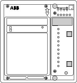
Operation indicators
I n = |
1A |
5A |
(I ) |
|
||
I n = |
0.2A |
|
1A |
(I o) |
fn = 50 / 60 Hz |
|
SPAJ 141 C
|
|
|
|
80...265V – |
|
|
|
|
|
|
|
|
||||
|
|
|
|
|
|
|
~ |
|
|
|
U aux |
|||||
|
|
|
|
18...80V – |
|
|
|
|||||||||
|
|
|
|
|
|
|
|
SPCJ 4D24 |
|
|
|
|
|
|
||
|
|
|
REGISTERS |
|
OPER.IND. |
|||||||||||
|
|
|
|
|
|
|
|
|
|
|
|
|
|
|
||
|
|
|
0 |
|
0 |
0 |
0 |
|
|
0 |
|
|
|
|
|
|
|
1 |
|
I L1 /I n |
|
|
1 |
I >START |
|||||||||
|
2 |
|
I L2 /I n |
|
|
2 |
I >TRIP |
|||||||||
|
3 |
|
I L3 /I n |
|
|
3 |
I >>START |
|||||||||
|
4 |
|
I max (15min) /I n |
4 |
I >>TRIP |
|||||||||||
|
5 |
|
t (I >)[ % ] |
5 |
I o>START |
|||||||||||
|
6 |
|
t (I >>)[ % ] |
6 |
I o>TRIP |
|||||||||||
|
7 |
|
I o [ % I n ] |
7 |
I o>>START |
|||||||||||
|
8 |
|
t (I o >)[ % ] |
8 |
I o>>TRIP |
|||||||||||
|
9 |
|
t (I o>>)[ % ] |
9 |
CBFP |
|||||||||||
0084A |
|
RS 611 |
|
|
|
Ser.No. |
|
|
|
|
|
|
||||
|
|
|
|
|
|
|
|
|
|
|
||||||
|
|
3 I |
> |
2 |
|
I |
|
|
|
|
|
5 |
I L1 I L2 I L3 |
I o IRF |
|
|
I > /I n |
RESET |
|
|
STEP |
|
|
|
t > [s] |
|
|
|
k |
|
|
|
I >>/ I n |
|
|
|
t >>[s] |
|
|
|
I o > [ %I n ] |
|
|
|
to >[s] |
|
|
|
I o >> [ %I n ] |
|
|
|
to >>[s] |
|
|
|
|
PROGRAM |
|
|
SGF |
|
|
|
SGB |
|
|
 SGR
SGR
TRIP
0085A |
SPCJ 4D24 |
A)The indicator TRIP is lit when one of the protective stages operate. When the protective stage resets, the red indicator remains lit.
B)If the display is dark when one of the pro-
tective stages I>, I>>, I0> or I0>> call for a tripping, the faulty phase or the neutral path is indicated with a yellow LED. If, for instance, the TRIP indicator glows red, and the indicators
IL1 and IL2 at the same time are illuminated, overcurrent has occurred on phase L1 and L2.
C)Besides being a code number at data presentation, the leftmost red digit or the display serves as a visual opetarion indicator. An operation indicator is recognized by the fact that the red digit alone is switched on. The following table named OPERATION IND. on the relay front panel is a key to the function code numbers used.
Indication |
Explanation |
|
|
|
|
1 |
I> START |
= The low-set stage I> of the overcurrent unit has started |
2 |
I> TRIP |
= The low-set stage I> of the overcurrent unit has tripped |
3 |
I>> START |
= The high-set stage I>> of the overcurrent unit has started |
4 |
I>> TRIP |
= The high-set stage I>> of the overcurrent unit has tripped |
5 |
I0> START |
= The low-set stage I0> of the earth-fault unit has started |
6 |
I0> TRIP |
= The low-set stage I0> of the earth-fault unit has tripped |
7 |
I0>> START |
= The high-set stage I0>> of the earth-fault unit has started |
8 |
I0>> TRIP |
= The high-set stage I0>> of the earth-fault unit has tripped |
9 |
CBFP |
= Circuit Breaker Failure Protection has operated |
|
|
|
D) The TRIP indications persist when the protective stage returns to normal. The indicator is reset by pushing the RESET/STEP push-but- ton.
Further, the indicators may be reset via the external control input 10-11 by applying a control voltage to the input, provided that the switch SGB/8 is in position 1.
The basic protective relay functions are not depending on the state of the operation indicators, reset or non-reset. The relay is permanently operative.
If a protective stage starts, but no tripping occurs because the energizing quantity goes below the starting level before the delay circuit times out, the starting indicators are normally automatically switched off. However, by means of the switches SGF2/1…4 the starting indications may be made persistant which means that they are to be reset by pushing the RESET/ STEP push-button.
The persistent indications are obtained through the following programming.
Switch SGF2/1 = 1
Starting indication on I> persistent
Switch SGF2/2 = 1
Starting indication on I>> persistent
Switch SGF2/3 = 1
Starting indication on I0> persistent
Switch SGF2/4 = 1
Starting indication on I0>> persistent
On delivery from the factory the switches SGF2/ 1…4 have the preset configuration 0.
E) Shortly after the internal self-supervision system has detected a permanent relay fault the red IRF indicator is switched on and the output relay of the self-supervision system operates. Further, in most fault situations a autodiagnostic fault code is shown in the display. The fault code is composed of a red figure 1 and a green code number which indicates what may be the fault type. The fault code persists until the STEP/ RESET button is pressed. When a fault code appears on the display, the code number should be recorded and stated when service is ordered.
8
Power supply and output relay module
To be able to operate the relay needs a secured auxiliary voltage supply. The power supply module forms the voltages required by the measuring relay module and the auxiliary relays. The withdrawable power supply and output relay module is located behind the system front panel, which is fixed by means of form cross-slotted screws. The power supply and output relay module contains the power supply unit, all output relays, the control circuits of the output relays and the electronic circuitry of the external control inputs.
The power supply and output relay module can be withdrawn after removing the system front
panel. The primary side of the power supply module is protected with a fuse, F1, located on the PCB of the module. The fuse size is 1 A (slow).
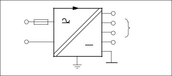
The power supply unit is a transformer connected, i.e. galvanically isolated primary and secondary side, flyback-type dc/dc converter. It forms the dc secondary voltages required by the measuring relay module; that is +24 V, ±12 V and +8 V. The output voltages ±12 V and +24 V are stabilized in the power supply module, while the +5 V logic voltage required by the measuring relay module is formed by the stabilizer of the relay module.
1 A slow |
+8V |
Unstabilized logics |
|
voltage |
|||
|
|||
|
|
||
Uaux |
+12V |
Operation amplifier |
|
|
|||
|
|
||
80...265 V ac & dc |
-12V |
voltage |
|
18...80 V dc |
|
||
|
Output relay coil |
||
|
+24V |
||
|
voltage |
||
|
|
Fig. 5.Voltage levels of the power supply module.
A green LED indicator Uaux on the system front panel is illuminated when the power supply module is in operation. The supervision of the voltages supplying the electronics is placed in the measuring module. If a secondary voltage deviates from its rated value by more than 25 %, a selfsupervision alarm will be established. An alarm is also received when the power supply module is withdrawn from the relay case, or when the auxiliary power supply to the relay is interrupted.
There are two versions of power supply and output relay modules available. For both types, the secondary sides and the relay configurations are identical, but the input voltage ranges differ.
Insulation test voltage between the primary and secondary side and the protective earth
2 kV, 50 Hz, 1 min
Rated power Pn |
5 W |
Voltage ranges of the power supply modules:
-SPTU 240 R1 Uaux = 80...265 V dc/ac
-SPTU 48 R1 Uaux = 18...80 V dc
(on request )
The SPTU 240 R1 module can be used with both ac and dc voltages. SPTU 48 R1 is designed for dc supply only. The system front panel of the relay indicates the auxiliary voltage range of the power supply module of the relay assembly.
9
Technical data
(modified 2002-04)
Energizing inputs
Rated current In
Overcurrent unit
Earth-fault unit
Thermal withstand capability
-continuously
-for 1 s
Dynamic current withstand, half-wave value Input impedance
Rated frequency fn
Rated frequency on request
Output contact ratings
Tripping contacts
Terminals
-Rated voltage
-Carry continuously
-Make and carry for 0.5 s
-Make and carry for 3.0 s
-Breaking capacity for dc, when the control circuit time-constant L/R < 40 ms, at 48 / 110 / 220 V dc
Signalling contacts
Terminals
-Rated voltage
-Rated current
-Make and carry for 0.5 s
-Make and carry for 3.0 s
-Breaking capacity for dc, when the control circuit time-constant L/R < 40 ms, at 48 / 110 / 220 V dc control circuit voltage
External control inputs
Blocking, remote reset or remote setting input External control voltage level
Typical control current of input circuit
Power supply and output relay module
Supply and relay module, type SPTU 240 R1 Supply and relay module, type SPTU 48 R1 Power consumption under quiescent/ operating conditions
|
1 A |
5 A |
0.2 A |
1 A |
|
2 A |
4 A |
20 A |
50 A |
100 A |
500 A |
100 A |
250 A |
1250 A |
<750 mΩ |
<100 mΩ |
<20 mΩ |
50 Hz |
|
|
60 Hz |
|
|
65-66, 74-75
250 V dc/ac
5 A
30 A
15 A
5 A / 3 A / 1 A
70-71-72, 68-69, 77-78, 80-81 250 V dc/ac
5 A
10 A
8 A
1 A / 0.25 A / 0.15 A
10-11
18...265 V dc or 80...265 V ac 2…20 mA
80...265 V dc/ac
18...80 V dc (on request)
4 W/ 6 W
10