- •Installation
- •Installation
- •Installation
- •Valve stem wear
- •Valve guide servicing
- •Valve seat width
- •Valve seat servicing
- •Valve seat cutter set
- •Valve seat cutter (n-608)
- •Initial seat cut
- •Valve stem end condition
- •Valve spring
- •Valve spring compressor attachment
- •Vernier calipers
- •V block
- •Inspection
- •If grease or oil is present on the surface of the drive
- •Inspection
- •It with a plastic mallet.
- •Its two ends to overlap in the groove.
- •Initial: 25 Nm (2.5 kgf-m, 18.0 Ib-ft)
- •8 Mm: Internal 10 n m (1.0 kgf-m, 7.0 Ib-ft)
ENGINE
41
•Tighten
the movable driven face ring nut to the specified
torque
with the special tool
Movable
driven face ring nut:
100
N-m (10.0 kgf-m, 72.5 Ib-ft)
TOOL:
Ring nut socket wrench
Fixed
driven face holder
DRIVE
BELT
Check
that the drive belt is free from any greasy substance.
Inspect
the contact surface of the drive belt for cracks or
damage
and measure the width of the drive belt using the
vernier
calipers.
If
any damages are found or the measurement exceeds the
service
limit, replace the drive belt with a new one.
DATA
Drive
belt width
Service
Limit: 35.7 mm (1.41 in)
TOOL:
Vernier calipers
CAUTION
belt,
degrease the belt thoroughly.
OIL
PUMP
Rotate
the oil pump by hand and check that it moves smoothly.
If
it does not move smoothly, replace the oil pump assembly.
CAUTION
The
oil pump case securing screw is applied with
THREAD
LOCK. If an attempt is made to overhaul the
pump
assembly, the screw may be damaged. Only
the
oil pump unit is available as a replacement.

Inspection
If grease or oil is present on the surface of the drive
ENGINE
42
TRANSFER
DISASSEMBLY
• Disassemble
the transfer as shown.
REASSEMBLY
Assemble
the transfer in the reverse
order
of disassembly. Pay attention to
following
points:
NOTE:
Always
use new snap rings.
NOTE:
Before
installing the gears, coat lightly
engine
oil to the transfer input/output
shaft.

ENGINE
43
CAUTION
• Never
reuse a snap ring. After a snap ring has been
removed
from a shaft, it should be discarded and a
new
snap ring must be installed.
• When
installing a new snap ring, care must be taken
not
to expand the end gap larger than required to
slip
the snap ring over the shaft.
• After
installing a snap ring, always ensure that it is
completely
seated in its groove and securely fitted.
• When
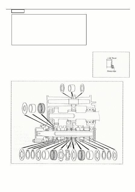
installing a new snap ring, pay attention to the directon
of
the snap ring. Fit it to the side where the thrust is as shown
in
figure.

ENGINE
44
SHIFT
FORK
SHIFT
FORK TO GROOVE CLEARANCE
Using
a thickness gauge, check the shifting fork clearance in the
groove
of its gear.
The
clearance for each of the three shifting forks plays an
important
role in the smoothness and positiveness of shifting
action.
If
the clearance exceeds the limit, replace the fork or its gear, or
both.
DATA
Shift fork to groove clearance
Standard:
0.10 - 0.30 mm (0.004 - 0.012 in)
Service
Limit: 0.50 mm (0.020 in)
TOOL:
Thickness gauge
Vernier
calipers
DATA
Shift fork groove width
Standard
(High/Low):
5.50
- 5.60 mm (0.217 - 0.220 in)
(Reverse):
5.50
- 5.60 mm (0.217 - 0.220 in)
DATA
Shift fork thickness
Standard
(High/Low):
5.30
- 5.40 mm (0.209 - 0.213 in)
(Reverse):
5.30
- 5.40 mm (0.209 - 0.213 in)

ENGINE
45
GEARSHIFT
CAM
DISASSEMBLY
•Disassemble
the gearshift cam as shown.
REASSEMBLY
•Install
the gearshift cams.
NOTE:
Align
the punched mark
○A
with the punched mark
○
1
For High/Low gear (Left side)
○
2
For reverse gear (Right side)
○
B

ENGINE
46
CRANKSHAFT
DISASSEMBLY
REASSEMBLY
• Determine
the width between the webs referring to the figure
when
rebuilding the crankshaft.
DATA
Crank web to web width
Standard:
71 ± 0.1mm

ENGINE
47
DRIVE
TRAIN (INBOARD SIDE)
CONSTRUCTION

ENGINE
48
REMOVAL
• Remove
the transfer assemblies.
• Remove
the front output shaft
○1
and rear output shaft
○2
.
• After
removing the drive bevel gear nut, remove the drive
bevel
gear and output driven gear.
• Separate
the front and rear output shafts.
DISASSEMBLY
Front
output shaft
• Remove
the C-rings from the universal joint.
CAUTION
Replace
the removed C-ring with a new one.
• Remove
the bearings by tapping with the special tool and
hammer.
TOOL
: Bearing installer set

ENGINE
49
• Remove
the washer and snap rings from the front output
shaft.

ENGINE
50
• Remove
the driven bevel gear and bearing-
Rear
output shaft
• Using
a chisel and unlock the nut.
• With
the rear output shaft held immovable with a vise,
remove
the nut.
CAUTION
Replace
the removed nut with a new one.

ENGINE
51
• Remove
the washer
○1
, joint yoke
○2
oil seal
○3
and
bearing
○4
.
CAUTION
The
removed bearing and oil seal must
be
replaced
with
the new ones.
Inspect
the front and rear output shafts for distortion. If distortion
is
found, replace the front or rear output shaft with a new one.

ENGINE
52
Inspect
the drive and driven bevel gears for wear or damage. If
any
wear or damage is found, replace the drive and driven bevel
gears
as a set.
REASSEMBLY
Reassemble
the front and rear output shafts in the reverse order
of
disassembly. Pay attention to the following points:
NOTE:
Before
reassembly, thoroughly clean all parts In cleaning solvent.
Front
output shaft
• Install
the bearing and driven bevel gear.
NOTE:
The
wider side
○A
of the bearing should be positionde bevel
gear
side.
• Install
the snap rings and washer.
• Install
the shim(s)
○1
and bearing
○2
.
NOTE:
The
bearing knock-pin
○A
should be positioned inside.

ENGINE
53
•
• Apply
grease to the lip of the oil seal.
• Install
the oil seal to the joint yoke.
NOTE:
The
lip
○B
of the oil seal should be positioned joint yoke side.
• With
the front output shaft held immovable with a vise,
tighten
the new nut to the specified torque.
Front
output shaft nut: 100 Nm (10.0 kgf-m, 72.5 Ib-ft)
NOTE:
Do
not stake a lock portion on the nut at this stage. After the
backlash
and tooth contact have been checked or adjusted,
stake
the nut with a center punch.

ENGINE
54
Rear
output shaft
• Install
the bearing to the shaft.
NOTE:
The
bearing knock-pin
○A
should be positioned inside.
• Apply
grease to the lip of the oil seal.
• Install
the oil seal to the joint yoke.
NOTE:
The
lip
○B
of the oil seal should be positioned joint yoke side.
• With
the rear output shaft held immovable with a vise,
tighten
the new nut to the specified torque.
Rear
output shaft nut: 100 N m (10.0 kgf-m, 72.5 Ib-ft)
Stake
the nut with a center punch.

ENGINE
55
• After
reassembling the universal joint, check the joint
movement
smoothly. If a large resistance is felt to
movement,
tap the bearing with a plastic mallet lightly.
Front/Rear
output shaft
• Align
the bearing rings with their grooves in the crankcase.
• Position
the knock-pin on the bearings to the pin grooves in
the
crankcase.

ENGINE
56
• Check
the front/rear output shaft to rotate smoothly.
SHIM
ADJUSTMENT
BACKLASH
• Install
the output driven gear and drive bevel gear.
• Place
the front and rear output shafts on the right crankcase
half
and hold bearings with the special tool.
TOOL:
Bearing holder
• Set
a dial gauge as shown on the drive bevel gear.
Measure
the backlash by turning the drive bevel gear shaft in
each
direction, reading the total backlash on the dial gauge. If
the
backlash is not within specification, the shim must be
changed
and the backlash should be re-checked until correct.
Refer
to the chart at the right for appropriate shim thickness.
DATA
Bevel gear backlash
Standard:
0.03-0.15 mm (0.001-0.006 in)
NOTE:
Adjust
the backlash by referring to the chart at the right and using
the
thickness of the removed shims as a guide.

ENGINE
57
TOOTH
CONTACT
After
backlash adjustment is carried out, the tooth contact must
be
checked. Pay attention to the following procedures:
• Remove
the front and rear output shafts from the crankcase.
• Clean
and degrease several teeth of the drive and driven
bevel
gears.
• Apply
a coating of machinist's layout dye or paste to several
teeth
of the driven bevel gear.
• Install
the front and rear output shafts.
• Rotate
the driven bevel gear several turns in both directions.
Remove
the output shafts and inspect the coated teeth of the
drive
bevel gear. The tooth contact pattern should be as
shown
in 1 , 2 and
○3
.
• If
tooth contact is found to be correct (example
○2
) ,go to
the
FINAL
ASSEMBLY section on to complete installation.
○
1
Incorrect (contact at tooth top)
○
2
Correct
○
3
Incorrect (contact at tooth root)
• If
tooth contact is found to be incorrect (examples (1) and
(3)),
the
shim thickness between the drive bevel gear and driven
bevel
gear must be changed and the tooth contact
re-checked
until
correct.
CAUTION
Make
sure to check the backlash after the tooth contact
has
been adjusted, since it may have changed. Adjust
the
tooth contact and backlash until they are both within
specification.
If the correct tooth contact cannot be
maintained
when adjusting the backlash , replace the
drive
and driven bevel gears.
○ ○
Tooth
contact
Contact
at tooth top 1
○
Contact
at tooth root 3
○
Shim
adjustment
Increase
shim thickness
Decrease
shim thickness

ENGINE
58
FINAL
ASSEMBLY
• After
adjusting the gear backlash and tooth contact correctly,
remove
the front and rear output shafts and drive bevel gear.
• Clean
off any machinist's dye or paste from the gear teeth,
and
lubricate the teeth with engine oil.
• Tighten
the front output shaft nut and drive bevel gear nut to
the
specified torque.
Front
output shaft nut: 100 Nm (10.0 kgf-m, 72.5 Ib-ft)
Drive
bevel gear nut: 100 N m (10.0 kgf-m, 72.5 Ib-ft)
TOOL:
Output shaft holder
• Stake
the collar of the nut
○1
into the notch in the shaft.

ENGINE
59
REASSEMBLY
INFORMATION

ENGINE
60
CRANKCASE
DRIVE
BEVEL GEAR REMOVAL
• Using
a chisel, unlock the nut.
• Remove
the drive bevel gear nut with the special tool.
TOOL:
Output shaft holder
• Remove
the washer
○1
and drive bevel gear.
• Remove
the shim
○2
and output driven gear.
• Remove
the output shaft with a plastic mallet.
DRIVE
BEVEL GEAR INSTALLATION
• Install
the output shaft with a plastic mallet.

ENGINE
61
• Install
the output driven gear.
• Install
the shim 1
○
• Install
the drive bevel gear and washer 2
○
• Tighten
the drive bevel gear nut to the specified torque with
the
special tool.
Drive
bevel gear nut: 100 N m (10.0 kgf-m, 72.5 Ib-ft)
TOOL:
Output shaft holder
• Stake
the nut with a center punch.
OIL
SUMP FILTER
• Remove
the oil sump filter cover
○1
.

ENGINE
62
• Remove
the oil sump filter
○1
.
• Clean
the oil sump filter by using compressed air.
• When
installing the oil sump filter, apply grease to the new
O-ring.
OIL
PRESSURE REGULATOR
• Remove
the oil pressure regulator
○1
.
• When
installing the oil pressure regulator
○1
, tighten it to
the
specified torque.
Oil
pressure regulator: 23 N m (2.3 kgf-m, 16.5 Ib-ft)
• Check
the operation oil the oil pressure regulator pushing
on
the piston with an appropriately shaped tool. If the
piston
does not operate, replace the oil pressure regulator
with
a new one.

ENGINE
63
BEARING
INSPECTION
Rotate
the bearing inner race by finger to inspect for abnormal
play,
noise and smooth rotation while the bearings are in the
crankcase.
Replace
the bearing in the following procedure if there is
anything
unusual.
BEARING
DISASSEMBLY
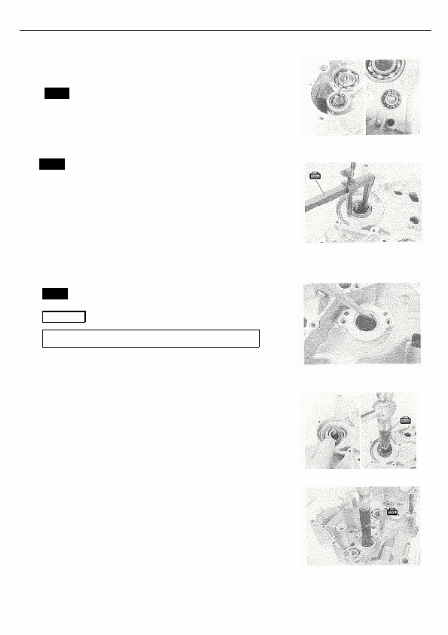
• Remove
the bearing retainers.
• Remove
the bearing with the special tool.
TOOL:
Bearing remover set
NOTE:
If
there is no abnormal noise, the bearing removal is not
necessary.
• Remove
the water pump drive shaft (1) by removing the
snap
ring.
TOOL:
Snap ring pliers

ENGINE
64
• Remove
the snap ring.
TOOL:
Snap ring pliers
• Remove
the bearing with the special tool.
TOOL:
Bearing remover set
BEARING
REASSEMBLY
• Install
the bearing with the special tool.
TOOL:
Bearing installer set
• Install
the bearing retainers.
NOTE:
When
installing the bearing retainers, apply a small quantity of
THREAD
LOCK to the screws.

ENGINE
65
• Install
the water pump drive shaft
○1
and snap ring.
TOOL:
Snap ring pliers
OIL
SEAL
• Remove
the oil seal with the special tool.
TOOL:
Oil seal remover
• Remove
the oil seal.
• Install
the oil seal with the special tool.
TOOL:
Bearing installer set
CAUTION
Use
the new oil seal to prevent oil leakage.
NOTE:
Thestampedmarkontheoilsealfacesoutside.

