ENGINE
30
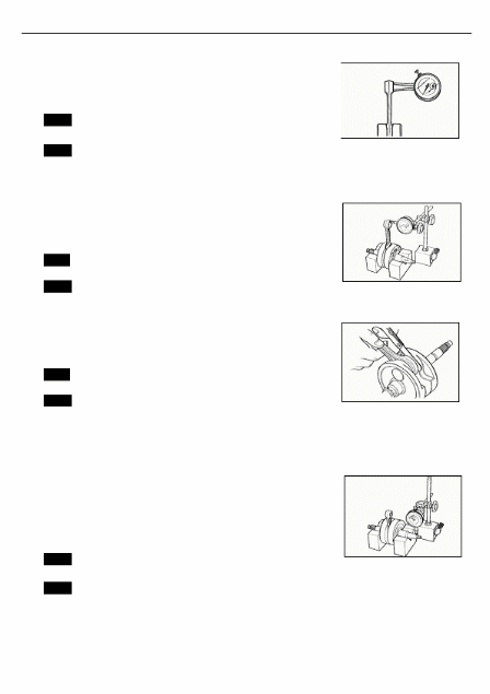
PISTON
RING FREE END GAP AND END GAP
Before
installing piston rings, measure the free end gap of each
ring
using vernier calipers. Next, fit the ring in the cylinder, and
measure
each ring end gap using a thickness gauge.
If
any ring has an excess end gap, replace the ring.
DATA
Piston ring free end gap
Service
Limit (1st) : 8.9 mm (0.35 in)
(2nd):
9.5 mm (0.37 in)
DATA
Piston ring end gap
Service
Limit (1st) : 0.50 mm (0.020 in)
(2nd):
0.50 mm (0.020 in)
TOOL
Thickness
gauge
PISTON
PIN AND PIN BORE
Using
a small bore gauge, measure the piston pin bore inside
diameter,
and using a micrometer, measure the piston pin outside
diameter.
It the reading exceeds following limit, replace both piston
and
piston pin.
DATA
Piston pin bore
Service
Limit: 23.030 mm (0.9067 in)
TOOL
Dial gauge (1/1000 mm, 1 mm)
Small
bore gauge (18-35 mm)
Using
a micrometer, measure the piston pin outside diameter at
three
positions.
DATA
Piston pin O.D.
Service
Limit: 22.980 mm (0.9047 in)
TOOL
Micrometer (0 - 25 mm)

Vernier calipers
ENGINE
31
CONROD/CRANKSHAFT
CONROD
SMALL END l.D.
Using
a caliper gauge, measure the conrod small end inside
diameter.
DATA
Conrod small end l.D.
Service
Limit: 23.040 mm (0.9071 in)
TOOL
Dial calipers (10-34 mm)
Small
bore gauge (18-35 mm)
If
the conrod small end inside diameter exceeds the above
mentioned
limit, replace the conrod.
CONROD
DEFLECTION
Wear
on the big end of the conrod can be estimated by checking
the
movement of the small end of the rod. This method can also
check
the extent of wear on the conrod's big end.
DATA
Conrod
deflection
Service
Limit: 3.0 mm (0.12 in)
TOOL
Magnetic stand
Dial
gauge (1/100 mm)
CONROD
BIG END SIDE CLEARANCE
Push
the big end of the conrod to one side and measure the side
clearance
with a thickness gauge,
DATA
Conrod big end side clearance
Service
Limit: 1.0 mm (0.04 in)
TOOL
Thickness gauge
If
the clearance exceeds the limit, replace the
crankshaft
assembly
with a new one or bring the deflection and the side
clearance
within the service limit by replacing the worn parts
(conrod,
big end bearing, crank pin, etc.) with new ones.
CRANKSHAFT
RUNOUT
Support
the crankshaft with "V" blocks as shown, with the two end
journals
resting on the blocks.
Position
the dial gauge, as shown, and rotate the crankshaft
slowly
to read the runout.
Correct
or replace the crankshaft if the runout is greater than the
limit.
DATA
Crankshaft runout
Service
Limit: 0.08 mm (0.003 in)
TOOL
Dial gauge (1/100 mm)
Magnetic
stand
V-block
set (100 mm)
V block
ENGINE
32
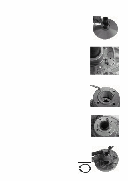
CLUTCH
CLUTCH
SHOES
Inspect
the clutch shoes for chips, cracks, uneven wear, and heat
discoloration.
Also, check the depth of the grooves on the clutch
shoes.
If there is no groove at any part of the shoes, replace the
shoes
as a set.
NOTE:
The
clutch shoes must always be changed as a set.
CLUTCH
WHEEL
Inspect
the condition of the inner clutch wheel surface for scuffs,
scratches,
cracks or uneven wear. If any damages are found,
replace
the clutch wheel with a new one.
CLUTCH
GUIDE BLOCK
Inspect
clutch of the guide block for wear or damage. If any
damages
are found, replace the oil seal with a new one.
• Remove
the guide block l with the special tool.
TOOL
The guide block
remover
STARTER
CLUTCH
• Remove
the starter clutch securing bolts with a offset wrench.

ENGINE
33
• Install
the starter clutch in the proper direction.
NOTE:
• When
installing the starter clutch onto the rotor, make sure the
flange
side
○A
of the one way clutch faces to the rotor.
• Face
the arrow mark
○B
to the engine side.
• Apply
engine oil to the starter clutch.
○
A
○
B
• Apply
THREAD LOCK SUPER "1303" to the bolts, and then
tighten
them to the specified torque with a offset wrench.
THREAD
LOCK SUPER "1303"
Starter
clutch bolt: 26 N m (2.6 kgf-m, 19.0 Ib-ft)
• Install
the starter driven gear to the starter clutch.
• Check
that the starter driven gear turns in the opposite direction
of
the arrow mark
○B
on the rotor while holding the generator
rotor.
The gear never turns in the direction of the arrow.
• If
there is anything unusual, replace the one way clutch.
• Check
the starter driven gear bearing. If there is anything
unusual,
replace the bearing.
• Remove
the bearing with the special tool.
TOOL
Bearing installer/remover set
• Install
the bearing with the special tool.
TOOL
Bearing installer/remover set

ENGINE
34
movable
drive face and driven face
○
A
Movable drive face nut
○
B
Movable driven face nut
○
○
2
Damper (4 pcs)
○
3
Spacer
○
4
Roller (8 pcs)
○
6
Movable drive face
○
5
Oil seal (2 pcs)
○
7
Drive belt
○
8
Fixed drive face
○
9
Fixed driven face
○
10
Washer
21
SPACER
1
Movable drive plate
○
11
Circlip(2 pcs)
○
12
Bush (2 pcs)
○
13
Movable driven face
○
14
The guide block
○
15
Washer (3 pcs)
○
16
Blot (3 pcs)
○
17
Spring
○
18
Pin
○
19
Spring seat
○
20
Circlip
ITEM
○
A
○
B
N.m
kgf-m lb-ft
115
115
11.5
11.5
83.0
83.0

ENGINE
35
MOVABLE
DRIVE FACE DISASSEMBLY
• Remove
the spacer.
• Remove
the movable drive face plate
○1
and rollers
○2
.
○
1
ROLLER
AND SLIDING SURFACE
2
○
Inspect
each roller and their sliding surface for wear or damage.
If
any damages are found, replace the rollers as a set.
NOTE:
The
rollers must always be changed as a set.
OIL
SEAL
Inspect
the lip of the oil seal for wear or damage. If any damages
are
found, replace the oil seal with a new one.
• Remove
the oil seal.

ENGINE
36
MOVABLE
AND FIXED DRIVE FACE
Inspect
the drive faces for any abnormal conditions such as
stepped
wear or discoloration caused by burning.
If
any damages are found, replace the drive faces with new ones
• Install
the oil seal with the special tool.
TOOL
:
Bearing install set
REASSEMBLY
Reassemble
the movable and fixed drive face in the reverse
order
of disassembly. Pay attention to the following points:
• Apply
a small amount of
lip.
GREASE
"A" to the bore and oil seal
CAUTION
• *
W
ipe off any excess grease thoroughly.
• *
T
ake care not to apply grease to the contact
surface
of the drive belt.
• Position
the eight rollers
○1
on the movable drive face.
• Mount
the damper
○2
on the movable drive face plate
○3
.
• Position
the movable drive plate on the movable drive face.
NOTE:
Press
down the movable drive face plate so as not to cause the
rollers
to come out of position when inserting the spacer.
○
1
○ ○
2
3

ENGINE
37
MOVABLE
DRIVEN FACE DISASSEMBLY
Hold
the movable driven face assembly with the special tool
and
vise, loosen the movable driven face circlip with the
special
tool.
WARNING
Do
not remove the movable driven face circlip
before
attaching the clutch spring compressor.
TOOL:
Circlip socket wrench
Fixed
driven face holder
• Attach
the special tool to the movable driven face assembly
and
compress the movable driven face assembly by turning in
the
special tool handle.
NOTE:
Make
sure to insert the spring end (A) into the slot (4) of the
special
tool as shown.
.
• Remove
the movable driven face circlip.
TOOL
: Movable driven face spring compressor
WARNING
Since
a high spring force applies to the movable driven
face,
care must be used so as not to cause the movable
driven
face to come off abruptly.
• Loosen
the special tool handle slowly and remove the special
tool.

ENGINE
38
①
• Remove
the spring seat ①
• Remove
the spring ②
②
• Remove
the pin ③
• Remove
the movable driven face ④
④
③
• Remove
the washer
• Remove
the guide block
O-RING
AND OIL SEAL
Inspect
the O-rings and oil seals for wear or damage. If any
damages
are found, replace the O-rings and oil seals with new
ones.

ENGINE
39
• Install
the oil seal with the special tool,
TOOL
: Oil seal installer set
TOOL
MOVABLE
DRIVEN FACE SPRING
Measure
the spring free length using the vernier calipers. If the
length
is shorter than the service limit, replace the spring with a
new
one.
DATA
Movable driven face spring free length
Service
Limit: 145.4 mm (5.72 in)
• INSTALL
the guide block
Measure
the guide block thickness using the vernier calipers. If the
thickness
is thin than the service limit, replace the guide block with
a
new one.
MOVABLE
AND FIXED DRIVEN FACE
Inspect
the driven face for any abnormal condition such as
stepped
wear or discoloration caused by burning. If any
damages
are found, replace the movable driven face with a new
one.

ENGINE
40
REASSEMBLY
• INSTALL
THE NEW WASHER
• INSTALL
THE SPRING BY ALIGING THE HOLE A
Install
the spring and spring seat by aligning the spring ends with the
holes
4
• Compress
the spring with the special tool
• INSTALL
THE PIN
• Tighten
the Movable driven face the circlip temporarily