

7 WiFi on the go to be available through Ford
There are many drivers who will know the feeling of wishing that they had internet or broadband access in the car so that they can get online whilst on a break from driving or so that passengers can get online to keep them occupied! In fact, WiFi on the move can come in useful for all sorts of things, from business to pleasure, which is why the new technology due to come in from car manufacturing giant Ford next year is set to be very popular.
It has been announced that the all new Ford Focus is set to prove very popular when Ford SYNC with MyFord Touch technology is launched in the UK next year. Owners of the car will be the first in the UK to benefit from the SYNC connectivity, which is also set to be rolled out to other vehicles in the Ford range over time.
Christof Kellerwessel, chief engineer for electronic and electrical systems, said: “Ford is an automaker that is quickly becoming a personal technology company as well. We’re finding that Ford customers are tech savvy and – while travelling as passengers in cars – they want to be able to use their WiFi enabled devices while on the move.”
He added: “A reliable in-car internet connection is therefore extremely important to them, and that’s exactly what SYNC will offer when it makes its UK debut on the Ford Focus in 2012. SYNC with MyFord Touch will offer rolling connectivity to Ford customers and everyone in a SYNC-equipped car can benefit at no additional expense.”
7.1 Why Microsoft Is Buying Skype for $8.5 Billion
Updated at 12 midnight. Microsoft has bought Skype for $8.5 billion, in an all-cash deal. The deal closed a few hours ago. is close to finalizing a deal to buy Skype for between $7 billion to $8 billion. The Wall Street Journal confirmed the news after we had first reported it yesterday. The announcement is likely to come out later today or tomorrow morning, according to several reports. Steve Ballmer, CEO of Microsoft, is said to be a big champion of the deal, the largest in the history of the company. Ballmer and Skype CEO Tony Bates will host a press conference in a few hours.
Skype has been up for sale for some time, thanks to some very antsy investors. My sources indicated both eBay and Silver Lake Partners have been getting nervous about the delayed initial public offering and have been pushing for a sale of Skype. Facebook and Google were said to be earlier dance partners for Skype, and Microsoft was a late entrant and is now close to walking away with the prize.
It won’t surprise me if Microsoft comes in for major heat on this decision to buy Skype — and the software company could always botch this purchase, as it often does when it buys a company. The Skype team is also full of hired guns who are likely to move on to the next opportunity rather than dealing with the famed Microsoft bureaucracy.
I also don’t believe Facebook and Google were serious buyers. Google, with its Google Voice offering, doesn’t really need Skype. In essence, I feel Microsoft was bidding against itself. Even then, I personally think this is a bet worth taking, especially for a company that has been left out in the cold for so long.
Skype gives Microsoft a boost in the enterprise collaboration market, thanks to Skype’s voice, video and sharing capabilities, especially when competing with Cisco and Google.
It gives Microsoft a working relationship with carriers, many of them looking to partner with Skype as they start to transition to LTE-based networks.
It would give them a must-have application/service that can help with the adoption of the future versions of Windows Mobile operating system.
However, the biggest reason for Microsoft to buy Skype is Windows Phone 7 (Mobile OS) and Nokia. The software giant needs a competitive offering to Google Voice and Apple’s emerging communication platform, Facetime.
7.2 Guess Who’s the Big Winner
The biggest winner of this deal could actually be Facebook. The Palo Alto, Calif.-based social networking giant had little or no chance of buying Skype. Had it been public, it would have been a different story. With Microsoft, it gets the best of both worlds: It gets access to Skype assets (Microsoft is an investor in Facebook) and it gets to keep Skype away from Google.
Facebook needs Skype badly. Among other things, it needs to use Skype’s peer-to-peer network to offer video and voice services to the users of Facebook Chat. If the company had to use conventional methods and offer voice and video service to its 600 million plus customers, the cost and overhead of operating the infrastructure would be prohibitive.
Facebook can also help Skype get more customers for its SkypeOut service, and it can have folks use Facebook Credits to pay for Skype minutes. Skype and Facebook are working on a joint announcement, and you can expect it shortly.
7.3 Why Did Skype Want To Sell?
Skype had filed for an IPO, was going to do about a billion dollars in revenues, and was on its way to becoming profitable. So why sell? Silver Lake and eBay were both getting impatient and wanted to lock in their profits. Some sources also believe Skype’s revenues had stalled.
The company had bet heavily on is video sharing service. The premium version of video calling and sharing was a way for Skype to increase its average revenue per user and move into the enterprise market. However, given Skype’s DNA is that of a consumer Internet company, the challenges aren’t a surprise.
7.4 So Who Made What?
Using the $8.5 billion price as the likely sale price, eBay gets $2.55 billion for its 30-percent stake in Skype. So in the end, eBay did make money on the Skype deal.
Patent
Abstact
For the better cooling of drive electronics, particularly distributed over a robot, and for avoiding mechanical and geometrical influences on the robot structure by the heating thereof as a result of the heat generated in the drive electronics, in the case of a robot with distributed drive elec¬tronics, the invention provides for each drive electronics to be connected in thermally insulated manner to the robot structure.


Field of the invention
The invention relates to a robot with drive electronics arranged in distributed manner.
Background of the invention
DE 198 46 960 A1 discloses a handling device on a plastics processing machine with on the latter drive motors associated in conventional manner with the parts to be driven, as well as a central control console on which are located both a central feed unit for supplying power to the drive motors and a central control unit for supplying the drive motors with control information.
It has repeatedly been proposed in the case of a robot to position electronic components, particularly components of the drive electronics, such as inverters, servo amplifiers, power semiconductors, drive circuits, ammeters and regulating circuits in distributed manner on the robot structure instead of centrally in a base or separate switch cabinet. As such power electronics generate heat, the heat dissipation problem arises. In view of the fact that the robot structure and the robot carrying elements are made from metal and the latter has a good thermal conductivity, it has been proposed that the power electronics be connected in good heat conducting manner to the robot structure or a gearbox and to dissipate or remove heat via the latter. The disadvantage is that the materials used have a considerable thermal expansion coefficient and therefore can lead to the heating of the robot structure or to different temperatures as a function of the loading condition and consequently to mechanical and geometrical changes. There can also be an increase in the motor temperature, which can lead to a power reduction and increased hazards in the case of contact, as well as to the gear temperature leading to a change in the lubricant and therefore to a reduction in the load carrying capacity and service life.
The same applies for the remote control device in the form of a manipulator according to DE 40 19 217 C2, where a printed circuit carrying electronic components is connected in heat conducting manner by means of the support to a metal base. Thus, here again the heat is dissipated by means of the supporting structure.
Therefore the problem of the invention is to provide an improved robot, whilst avoiding the indicated disadvantages.
Summary of the invention
According to the invention the set problem is solved in the case of a robot of the aforementioned type in that each drive electronics is thermally insulated with respect to the robot structure and is provided with a cooling device.
Thus, according to the invention the heat generated by the drive electronics distributed over the robot structure in the form of a drive amplifier is not introduced into the robot structure or parts thereof and instead is removed via the cooling device, which is separate to the robot structure, directly into the environment, so that there are no mechanical and geometrical changes to the robot structure due to the thermal expansion coefficients of the material thereof.
According to a preferred development each drive electronics is also mechanically connected to a passive cooling device associated therewith and in particular each drive electronics is held on the robot by means of its cooling device.
The cooling device can be constructed in different ways. However, in a preferred development the cooling device has a cooling body, particularly with cooling ribs or plates.
According to preferred developments of the invention, the cooling body has a fastening edge and by means thereof is fastened to the robot and the cooling device is in particular secured to the robot accompanied by the interposing of a thermal insulator. From the outset it is also possible for the fastening edge to be thermally insulated against the cooling body. In this case no separate thermal insulation is required. The thermal insulation can also be integrated into the fastening edge on the cooling body.
So that the complete robot contour takes not take up an excessive amount of space as a result of the decentral distribution of drive electronics thereon, particularly on the rocker arm and at the same time to utilize the contour and shape resulting from the necessary construction of the robot structure or the individual mechanical robot elements, according to a further development of the invention a drive electronics projects into a recess or a cavity of the robot structure and then fulfils the function of a housing (of a conventional control cabinet) and therefore mechanically protects and electrically shields the drive electronics, thereby ensuring a corresponding protective system particularly according to IP 67, so that the drive electronics can be constructed in casing-free manner, without any complicated casing.
According to another preferred development the mechanical connection of the drive electronics, which can take place by means of the fastening edge of the cooling device to the robot structure is separated from the electrical contacting of the drive electronics with its electric power supply lines. IN a preferred development a breadboard connected to the supply cables is provided having plug contacts by means of which the drive electronics is electrically contacted.
Alternatively either the breadboard is connected directly to the robot structure or the cooling device is fastened, whilst interposing the breadboard, with the latter to the robot structure.
As stated, the drive electronics in particular include power semiconductors and the circuit parts directly associated therewith such as drive units, ammeters and a microprocessor, which generates PWM signals, which implements the current regulation, the necessary monitoring and communications with the control means. An intermediate circuit supply unit can be implemented both centrally, e.g. in the drive box on the carousel or distributed over all the drive electronics. The invention permits a cost saving, open construction of the drive amplifier and the use of inexpensive connectors for connection to the back plane. For the cables running in the interior and the connectors it is possible to use inexpensive constructions. As a result of the plugging principle a simple replaceability of the drive amplifier is possible and servicing is greatly facilitated. It is also possible for two or three low power drive amplifiers to be mechanically combined into a unit, which leads to cost and space savings through the omission or joint use of some parts.
Brief description of the drawings
Further advantages and features of the invention can be gathered from the claims and the following description of an embodiment of a robot according to the invention with reference to the attached drawings, wherein show:
FIG. 1A perspective side view of a robot according to the invention.
FIG. 2 A side view of the robot of FIG. 1 from the side remote from the latter.
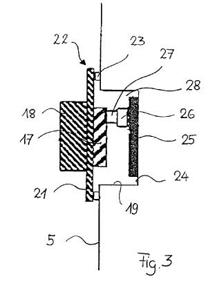
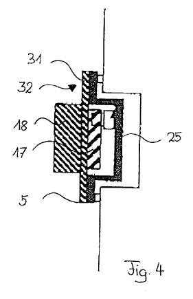
FIGS. 3 & 4 Diagrammatic representations concerning the integration of drive electronics in the robot structure on a robot arm.
FIG. 5 A perspective exploded view of a rocker arm with drive electronics and cooler body.
FIG. 6 A representation of the drive electronics for rotary and rocker arm drive on the robot carousel.
Detailed description of the drawings
A robot 1 according to the invention, such as the six-axis robot shown, has the conventional structure or conventional mechanical construction of such a robot. The rotary carousel 3 is located on a base 2. The carousel inter alia carries a bearing part 4 for a rocker arm 5 on which the robot arm 6 is pivotably mounted about the A3 axis. The arm 6 carries the robot hand 7, which is itself pivotable about the A4 axis aligned with the axis of arm 6 and further elements pivotable about the A5 and A6 axis.
The carousel 3 also carries a drive motor 11 for pivoting the carousel 3 about the vertical Al axis. On the bearing part 4 of carousel 3 is provided a drive motor 12 for pivoting the arm 5 about the Al axis. The carousel 3 carries a weight compensation 13 in the form of a spring. In the articulation 14 of arm 6 on rocker arm 5 is provided a drive motor 15 for pivoting the arm. On its side remote from the hand 7 the arm 6 carries drive motors 16, 16я, 16b for moving the hand 7 and the individual parts thereof.
The robot according to the invention also has drive elements or drive electronics 17, 41, 42, 51, 52, 53 arranged in distributed or decentral manner on the structure, which in particular can in each case comprise an inverter with an intermediate circuit supply unit, a resolver digital converter and ballast resistor or feedback module, optionally also a low voltage supply unit and electronics such as a control means, as well as installation locations for the integration of further electronic subassemblies. The latter are integrated into the robot structure and in the represented embodiment the drive electronics 17 for the drive motors 15 to 16b are distributed in the rocker arm 5 (FIGS. 3 and 4).
As can in particular be gathered from FIG. 5, the drive electronics for heat dissipation are provided on their side facing outwards with passive cooling devices and cooling bodies in the form of cooling ribs, cooling rods, etc.
For the reception of the drive electronics 17 in the robot structure are provided in the rocker arm 5 recesses or depressions 19 in which are embedded the drive electronics 17.
For holding or retaining drive electronics 17 with the associated cooling device 18 a fastening edge is provided from which projects inwards the drive electronics 17 and outwards the cooling device 18.
The fastening edge 21 is secured to the robot structure, here the rocker arm 5, outside the depression 19 and namely at location 22, whilst interposing a thermal insulator 23. Fixing can take place by means of screws, etc.
On the bottom 24 of the depression 19 of the robot structure (rocker arm 5) is provided a back plane or breadboard 25, which carries plug-in connections 26 for the electrical connection to a corresponding plug-in connection 27 on the drive electronics 17 for forming a connector 28 provided by both connections 26, 27.
In the construction of FIG. 4 the breadboard 25, unlike in the construction of FIG. 3, is not planar and directly connected to the bottom 24 of the depression 19. In FIG. 4 the breadboard 25 is constructed in U or cup-shaped manner and has an outwardly turned circumferential edge 31 with which it engages under the fastening edge 31, so that via the edge of the breadboard 25 it is fixed to the robot structure 5.
Alternatively a breadboard is freely movable with respect to the cooling device. For this purpose the breadboard as a result of an adequate length reserve of the connected cable for producing the plug connection can be drawn so far out of the interior of the robot structure that plugging in can take place with a mechanically released connection in order on the one hand to avoid undesired forces by aligning problems during plugging in and on the other to permit plugging to take place with good vision conditions.
Through the inventive solution of providing active cooling devices or passive cooling devices with cooling bodies directed outwards from the robot structure in the form of cooling ribs, cooling rods, etc. an effective heat dissipation of the heat generated by the drive electronics is obtained and therefore an effective cooling or heat removal with respect to the drive electronics, whilst avoiding any heat dissipation via the robot structure so as to bring about a heating of the latter and which could lead to mechanical and geometrical imprecisions. This is in particular aided by the fact that the drive electronics are mechanically fixed to the robot structure in such a way that the cooling device is thermally insulated by it.
In FIG. 141, 42 indicate axial amplifier modules provided with cooling devices 41, 42 which can be fixed or are fixable in the manner described hereinbefore to the robot structure, here in carousel 3. As can also be gathered from FIG. 1, on the carousel 3, namely laterally of the bearing part 4, there is a drive box 51 with jointly used subassemblies, such as e.g. a low voltage supply unit, which is provided with a cooling device 52.