

NATIONAL AVIATION UNIVERSITY
Airspace Institute
Mechanical-energy | Faculty
“Thermodynamics, Heat and mass Transfer”
Method for Brayton cycle calculation For students of Specialty “Gas Turbine Plants And Compressor Stations” brayton cycle calculation
T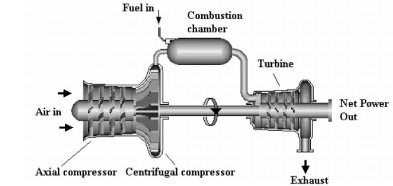 he
basic gas turbine cycle is named for the Boston engineer, George
Brayton, who first proposed the Brayton cycle around 1870.
Now, the
Brayton cycle is used for gas turbines only where both the
compression and expansion processes take place in rotating machinery.
he
basic gas turbine cycle is named for the Boston engineer, George
Brayton, who first proposed the Brayton cycle around 1870.
Now, the
Brayton cycle is used for gas turbines only where both the
compression and expansion processes take place in rotating machinery.
The ideal and basic Brayton cycle and is also known as the constant pressure cycle because the heating and cooling processes are conducted at constant pressure. A simple layout is shown on Fig.1.
Fig.1. Layout chart of gas turbine engine
The gas turbine engine is essentially a heat engine using air as a working fluid to provide thrust. To achieve this, the air passing through the engine has to be accelerated; this means that the velocity or kinetic energy of the air is increased. To obtain this increase, the pressure energy is first of all increased, followed by the addition of heat energy, before final conversion back to kinetic energy in the form of a high velocity jet efflux. These changes of state of working fluid which take place in any heat engine are named operation processes. Taken as a whole all this, processes are named as engine operating cycle.
A Brayton cycle is the basis for the operation of a gas turbine and can be used to approximate the cycle of all such units. A jet engine operates with an open cycle, which means fresh gas is drawn into the compressor and the products are exhausted from the turbine and not reused. It is important to remember that the compressor and turbine are on the same shaft, and thus power is extracted from the fluid by the turbine and used to drive the compressor.
Gas turbines usually operate on an open cycle, as shown in Fig.2.
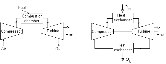
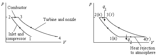
Fig.2. An open cycle gas-turbine engine Fig.3. A closed cycle gas-turbine engine
Fresh air at ambient conditions is drawn into the compressor, where its temperature and pressure are raised. The high-pressure air proceeds into the combustion chamber, where the fuel is burned at constant pressure. The resulting high-temperature gases then enter the turbine, where they expand to the atmospheric pressure through a row of nozzle vanes. This expansion causes the turbine blade to spin, which then turns a shaft. The exhaust gases leaving the turbine in the open cycle are not re-circulated.
The open gas-turbine cycle can be modeled as a closed cycle as shown in Fig.3 by utilizing the air-standard assumptions. Here the compression and expansion process remain the same, but a constant-pressure heat-rejection process to the ambient air replaces the combustion process. The ideal cycle that the working fluid undergoes in this closed loop is the Brayton cycle, which is made up of four internally reversible processes:
1-2 (н-к) - Isentropic compression (in a compressor)
2-3 (к-г) - Constant pressure heat addition
3-4 (г-т) - Isentropic expansion (in a turbine)
4-1 (т-н) - Constant pressure heat rejection
It assumed that the mass and the specific heats are the same for the heater and cooler.