

Text 2b. Rate Gyro and General Tests
Look through text 2B and speak on the general gyro tests. Use the
following questions as a plan:
what is usually checked in these tests?
what is a controlled rotating table?
what is an oscillating table used for?
which other tests can be performed on gyros?
The most important parameter checked on rate gyros is the accuracy of rate measurement. A controlled rotating table (a rate table) is used to calibrate rate gyros. This is done by mounting the gyro on the table with the input axis parallel to the axis of rotation. Various rates are set into the table and the rate gyro output is measured. An oscillating table is used to measure the natural frequency and damping characteristics of the rate gyro. Generally, this is done by comparing the phase of the gyro output signal with the phase of a velocity pickoff mounted on the oscillating table, as the frequency of oscillation is varied. A phase difference of 90 deg occurs when the table is being oscillated at the gyro natural frequency. A somewhat simpler test is to compare the phase of the gyro output signal with the phase of a position pickoff mounted on the oscillating table. Here, a phase difference of 0 deg is obtained when the table frequency equals the rate gyro natural frequency. The shape of the phase shift versus the table oscillating frequency curve is determined by the rate gyro damping.
These are the main gyro tests. However, gyros are checked for a variety of other things, including pickoff and torquer sensitivity, power consumption, damping control, rotor bearing condition (by determining motor run down time), axis alignment and cross-coupling, sensitivity to angular and linear acceleration and velocity, vertical and directional accuracy, resolution, threshold and hysteresis. Gyros are periodically checked to determine performance under extreme environmental conditions of temperature, humidity, vibration and shock.
UNIT 3
Essential vocabulary:
bellows,n – гофрированная трубка, пневматический амортизатор
blanket,n – покрытие, поверхностный слой, защитный слой
factor,n – множитель, коэффициент, показатель, фактор
housing,n – корпус, кожух
ratio,n – отношение, пропорция, коэффициент, степень
sleeve,n – втулка, муфта, цилиндр, барабан, корпус
contract,v – уплотнять, сжимать, стягивать
eliminate,v – устранять
expand,v – расширять
Incorporate,V – соединять, помещать, включать, монтировать
maintain,v – поддерживать
slope,v – наклоняться, иметь наклон
warrant,v – подтверждать, гарантировать
ambient,adj – окружающий
tight,adj – плотный, тугой, посаженный наглухо
back and forth – взад и вперед
conversely – напротив, наоборот
thereby – таким образом, в связи с этим
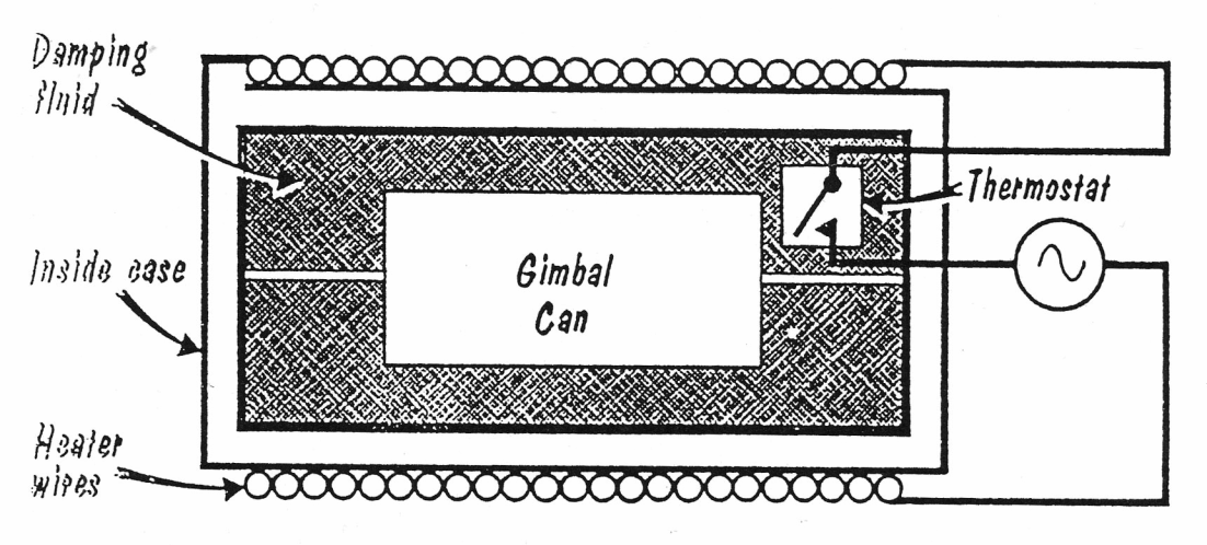
Text 3a. Temperature Control for Constant Damping
One approach is to operate the gyro at a constant temperature, thereby keeping the fluid viscosity constant. Such gyros incorporate a thermostat set to open above the maximum ambient temperature (see Fig. 5). If the gyro were to be used to +200 deg F, the thermostat might be set to open at +210 deg F. At temperatures below 210 deg F, the thermostat is closed and power is applied to a heating blanket surrounding the gyro. The gyro is then heated until the temperature is high enough to open the thermostat and stays open until the gyro cools down enough to close the thermostat again.
Using such a control, the temperature can be maintained constant within about plus or minus 5 deg F. This variation in temperature is usually small enough to keep the fluid viscosity constant enough for most applications. Damping can be held constant within plus or minus 5 percent of the nominal value. Such heater controls require a lot of power – about 100 to 200 watts-which may not be readily available.
|
Fig. 5. |
A number of mechanical means have been devised to reduce the damping variation with temperature. These are all aimed at eliminating the heater and thermostat. One method makes use of the fact that different materials expand at different rates with temperature. Nylon, for example, expands about 4 times more than does aluminium over the same temperature range. By placing a nylon sleeve over the gimbal and fabricating the housing from aluminium, the damping gap can be made to change by a factor of 4 to 1 while the fluid viscosity is changing by a factor of 15 to 1.
The arrangement is such that the gap gets smaller when the fluid gets less viscous. Therefore, the net change in damping is only about 4 to 1 instead of 15 to 1. In some applications, even the 4 to 1 damping change is too great, but still the very tight control obtained with a heater is not warranted.
Another system uses the fact that the fluid volume changes with temperature. When the fluid is heated and the viscosity decreases, the fluid expands. Conversely, when the fluid is cooled and the viscosity increases, the fluid contracts.
All fluid-filled rate gyros must compensate for the change in fluid volume with temperature. This is commonly done by including a bellows in the case. One damping compensator uses the bellows to drive a cylinder back and forth in the damping gap. The cylinder is made with spring fingers which press against the inside case and surround the gimbal can. Sloping surfaces are cut into the case. As the fluid expands, the bellows compress, and the spring cylinder is compressed by the sloping surfaces into a smaller diameter. This, in turn, reduces the damping gap between the spring cylinder and the gimbal. When the fluid contracts, the bellows expand. This causes the spring cylinder to expand and enlarges the damping gap.
In one such design, the damping gap changes by a ratio of 10 to 1 over the operating temperature. Since the fluid viscosity changes by 15 to 1 over the same range, the net change in damping is about 1.5 to 1.