Московский государственный технический университет
имени Н.Э. Баумана
И. А. БЕЛОВА, Е. Н. ШИШКИНА
МЕТОДИЧЕСКИЕ УКАЗАНИЯ
ПО ОБУЧЕНИЮ ЧТЕНИЮ
НАУЧНО-ТЕХНИЧЕСКОЙ ЛИТЕРАТУРЫ
НА АНГЛИЙСКОМ ЯЗЫКЕ ПО СПЕЦИАЛЬНОСТИ
«ПРИБОРЫ И СИСТЕМЫ ОРИЕНТАЦИИ,
СТАБИЛИЗАЦИИ И НАВИГАЦИИ»
Часть 2 г. Москва
2008 г.
УДК 531.01 Англ.
Б43
Рецензент к.Т.Н. Малахов а. А.
Б43 |
Белова И.А., Шишкина Е.Н. Методические указания по обучению чтению научно- технической литературы на английском языке по специальности «Приборы и системы ориентации, стабилизации и навигации». Часть 2. – М.: МГТУ им. Н.Э. Баумана, 2008. – 33 с., ил.
|
Содержат оригинальные тексты, знакомящие студентов с наиболее часто встречающейся терминологией по специальности, а также представляющие интерес с точки зрения грамматики – в них используются распространенные в технической литературе грамматические конструкции и обороты.
Предназначены для студентов младших курсов специальности «Приборы и системы ориентации, стабилизации и навигации».
УДК 541.01 Англ.
МГТУ им. Н. Э. Баумана, 2008
Contents
UNIT 1 |
4 |
TEXT 1A. THE RATE GYRO |
4 |
TEXT 1B. FIGURE OF MERIT |
10 |
UNIT 2 |
11 |
TEXT 2A. DAMPED OSCILLATIONS |
12 |
TEXT 2B. RATE GYRO AND GENERAL TESTS |
16 |
UNIT 3 |
17 |
TEXT 3A. TEMPERATURE CONTROL FOR CONSTANT DAMPING |
18 |
TEXT 3B. CROSS-COUPLING ERROR |
21 |
TEXT 3C. COMPENSATED ROLL PENDULUM |
22 |
SUPPLEMENTARY TEXTS FOR READING AND TRANSLATION |
26 |
1. THE EARTH IS A GYROSCOPE |
26 |
2. RIFLING |
27 |
3. BIKES, HOOPS AND TOPS |
27 |
4. SHIP STABILIZERS |
28 |
5. GYROSTABILIZED CARS |
29 |
6. BINOCULAR STABILIZER |
29 |
7. INTEGRATING ACCELEROMETER |
30 |
8. DIRECTION FINDERS |
31 |
9. REMEMBER GYROSCOPICS |
32 |
QUESTIONS AND PROBLEMS |
32 |
|
|
UNIT 1
Essential vocabulary.
drift,n – снос
random torque,n – случайный момент
reading,n – показание
reference line,n – линия условного уровня, контрольная линия, опорная линия
spring member,n – упругий элемент
stall torque,n – опрокидывающий момент
stretch,n – вытягивание, растягивание, удлинение
be subjected to,v – подвергаться чему-либо
consume,v – потреблять
extend,v – расширяться
imply,v – предполагать, подразумевать, заключать в себе, значить
refer to,v – ссылаться на
restrain,v – сдерживать
bilateral,adj – двунаправленный, двухсторонний
captive,adj – дочерний, подчиненный
for some comparison – для некоторого сравнения
in conjunction with – в связи с, в сочетании с
Text 1a. The Rate Gyro
The vertical and directional gyros are commonly called displacement gyros. These units measure the angular displacement or rotation of a base surface about some stabilized reference line. Control systems used in conjunction with displacement gyros utilize a torque in – precession out relationship. Various controlling torques are applied to cause the stabilized reference line to precess to a particular position. The torque in – precession out relationship determines the quality of the gyro. Random torques produce unwanted random drifts which affect the precision of the gyro.
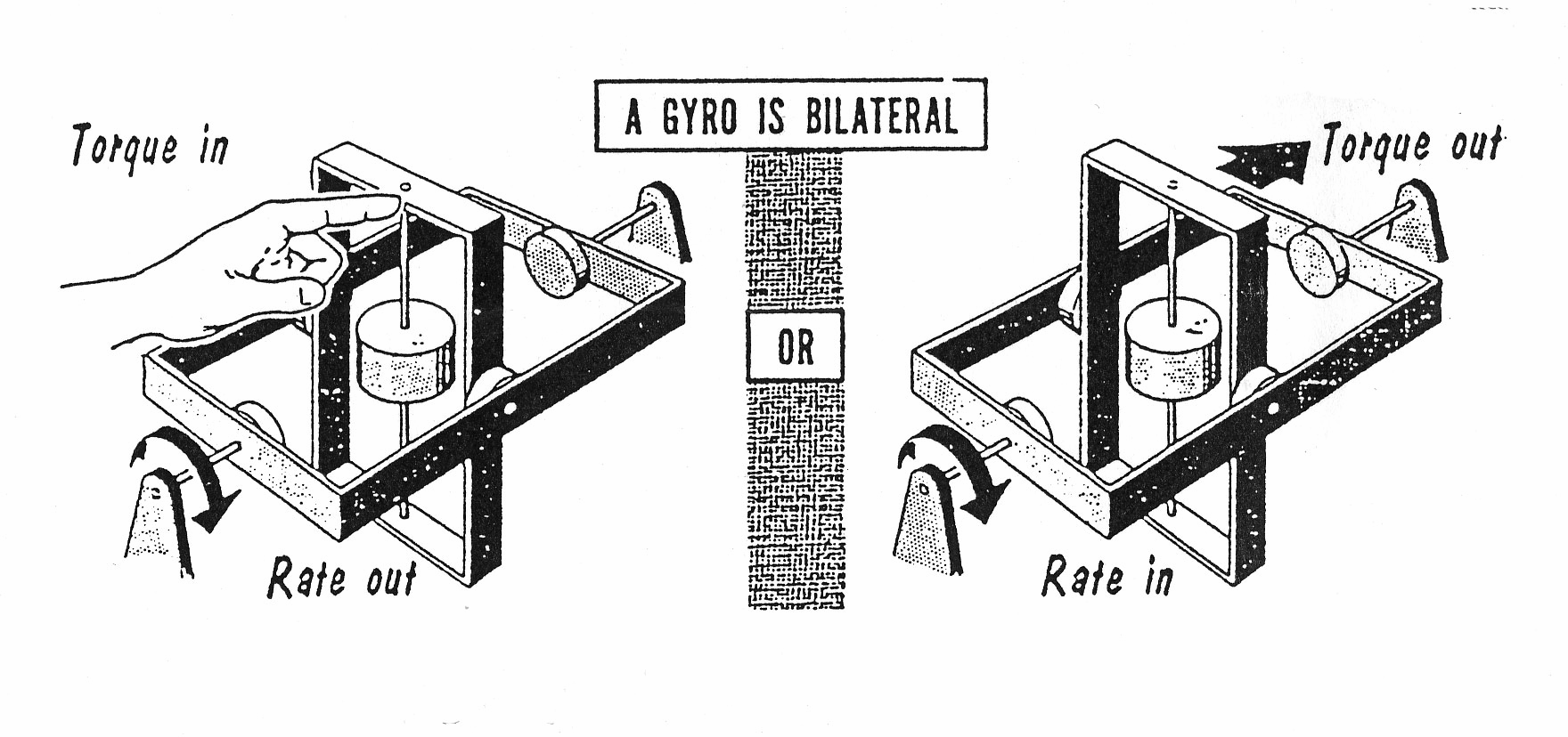
If you started with precession or angular rate, you could figure out the applied torque. This implies an interesting concept: if a gyro is subjected to any angular rate, a torque about the quadrature axis will be developed. In other words, a gyro is a bilateral device, as a torque input produces an angular rate output (torque in – precession out), and an angular rate input produces a torque output (precession in –torque out). The rate in – torque out relationship is the basis of the rate gyro (Fig. 1).
|
Fig. 1. |
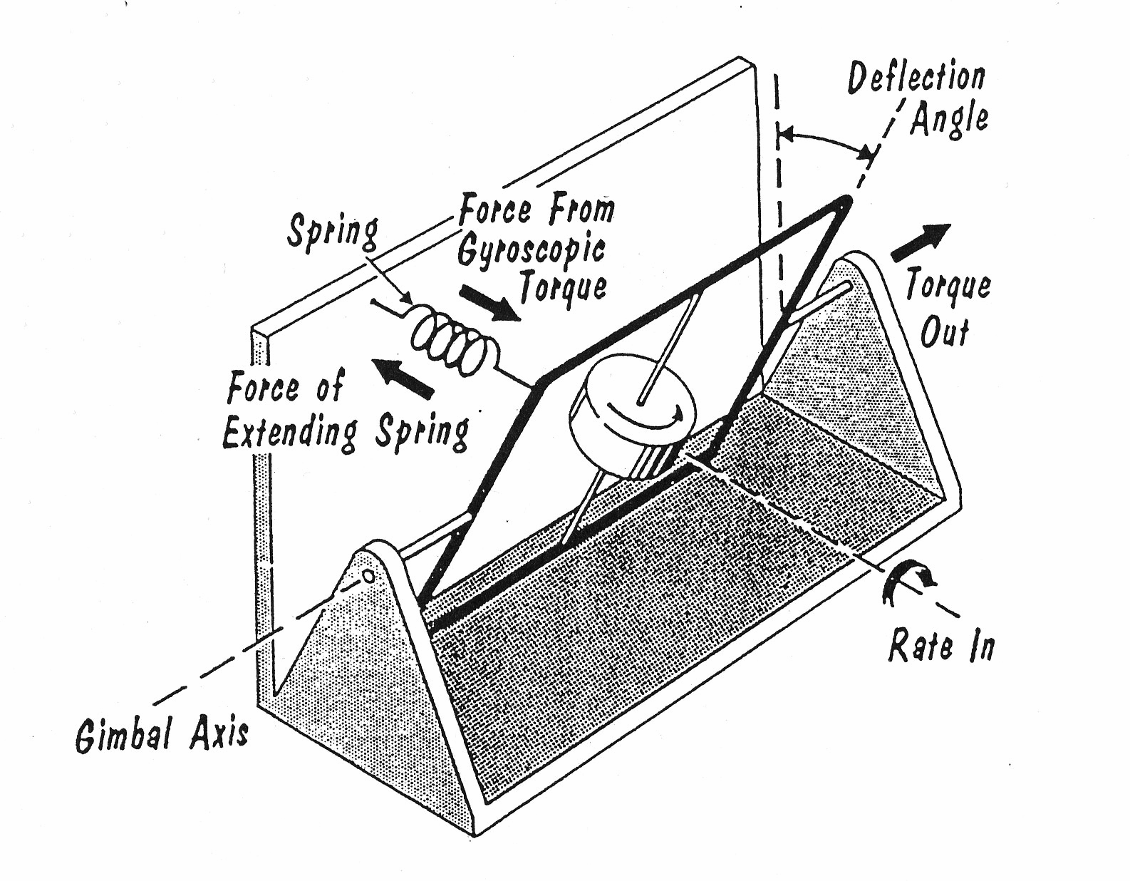
Consider what would happen to the single-degree-of-freedom gyro if subjected to an angular rate about the quadrature axis. The indicated torque would be developed about the gimbal axis. Instead of permitting complete freedom of movement about the gimbal axis, let us connect a spring member (as shown) between the gimbal and the base. See Fig. 2.
The gimbal rotates about the gimbal axis until the torque developed by the extending spring just balances out the gyroscopic torque developed from the input angular rate.
|
Fig. 2. |
The force developed by a spring is proportional to the stretch (compression). If the direction of the input angular rate is reversed, the gimbal will rotate against the spring in the opposite direction. Therefore, the angle of rotation about the gimbal axis is a measure of the input angular rate. If a pickoff is arranged to measure this gimbal angle, the pickoff reading will be proportional to the input angular rate.
The result is a gyro which instead of measuring displacement from a reference line measures the rate-of-change of displacement about a line (or axis). This is a rate gyro. Because the gimbal of the rate gyro is restrained by a spring, it is sometimes referred to as a captive gyro. Basically, the introduction of a spring member changes a displacement gyro into a rate gyro.
Rather large torques are developed in a rate gyro. A reasonable value of H for a rate gyro is about 5 x 10⁵ dyne-cm2/sec. If this unit is used to measure a rate of 100 deg/sec, a gyroscopic torque of about 13 oz-in is developed. A rate gyro rotor developing this torque would be about 11/2 in diameter by about 11/2 in long, and consume about 7 watts of power. For some comparison, a standard servo motor of about the same size has only 0.1 the stall torque (1.4 in-oz) for about twice the power input (12 watts).
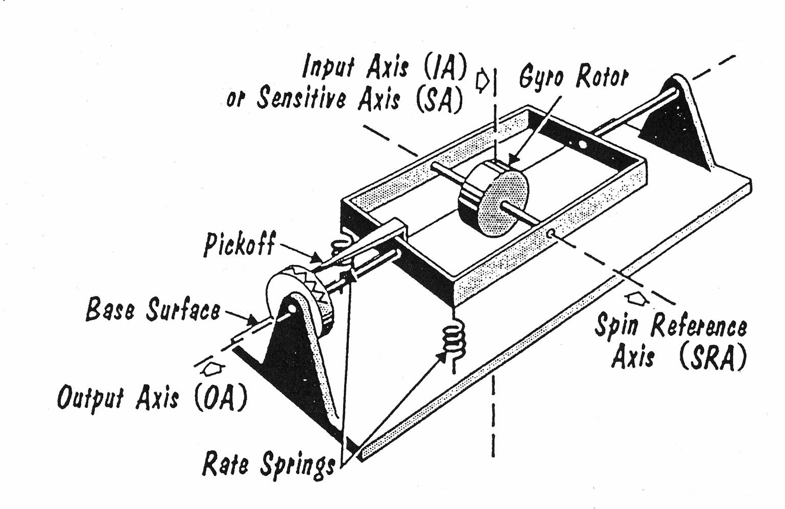
The axis about which the spin motor of a rate gyro rotates is called the spin reference axis (SRA). The axis about which the gimbal rotates is called the output axis (OA). The axis about which the rate gyro measures angular velocity (angular rate) is called the sensitive axis (SA) or input axis (IA). See Fig. 3.
|
Fig. 3. |