Setup AutoCad® Plant 3d
Other than AutoCAD® P&ID there is not much you can configure with AutoCAD® Plant 3D. However we will go through the step where you can lay your hands on.
A lot of configuration is done for AutoCAD® Isometrics. And of course specs and catalogs.
There are a lot of differences between AutoCAD® P&ID and AutoCAD® Plant 3D if it comes to the class structure. Between the Line Group and the Assets there are no Line Segements.
Step 1: Analyze and compute the info from your checklist
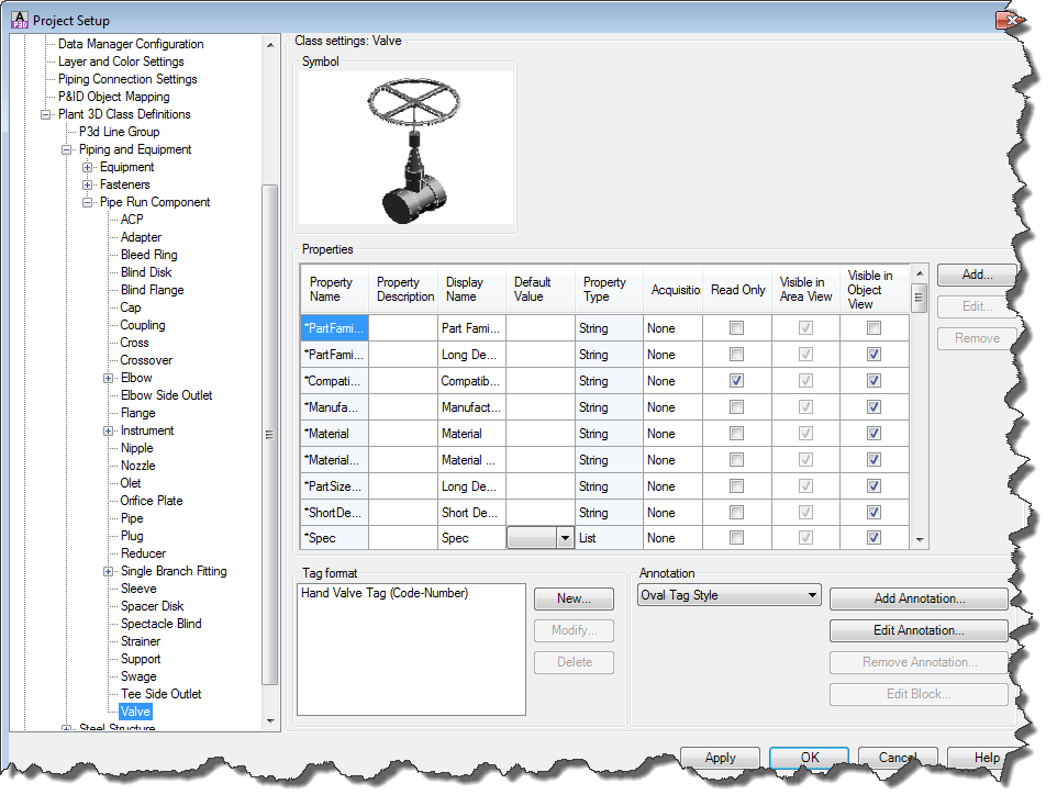
As with AutoCAD P&ID the Project Setup looks familiar. We see Classes, Properties, Tags and Annotations.
Step 2: Create properties, acquisition rules and selection lists
Properties
The classes are already defined and can’t really be extended. The class, to which an Asset belongs too, is predetermined by the catalog.
You can of course create additional properties. The same rules apply as with AutoCAD® P&ID.
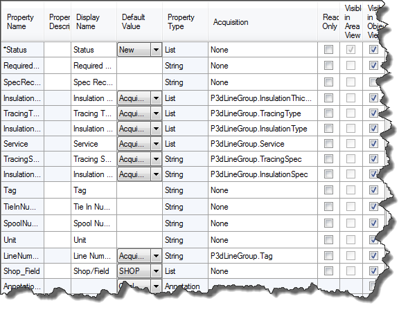
Acquisition Rules
Other than AutoCAD® P&ID creating Acquisition Rules in AutoCAD® Plant 3D is very restricted.
There are a bunch of rules pre-defined for PipeRunComponents. You can also add you own Acquisition Rules, but you are more or less limited to acquiring from the P3d Line Group.
Step 3: Create template drawings (DWT)
Template drawings are actually used for different types of drawings. One being for the 3D drawings themselves the other is for Ortho drawings. For the 3D source drawings you usually don’t need to worry about too much. Maybe setup your AutoCAD® grid and snap and some other standard AutoCAD® settings.
More important are the drawing templates for your deliverables in this case for your Orthos.
The drawing template which will be used when creating a new drawing are set under Paths.

There are also drawing templates for Isos, but they are defined in the Isometric DWG Settings of Project Setup.
Like with AutoCAD® P&ID you can define the drawing template any way you want and use the Field command again to have the title block filled out with Project and Drawing properties.
Step 4: Create Tags and Annotations
Tags
There are some classes where a Tag is and can be defined.
P3d Line Group, Equipment, Instrument, Nozzle, Support and Valve.
You can of course add your own Tag Formats or change the existing ones.
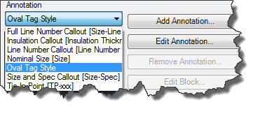
Annotations
Annotations are used if you want to annotate the objects (usually Equipment, Pipe Lines and/or Valves) in Orthos.
For PipeRunComponents there are already a lot of different types of Annotations.
Step 5: Create Catalogs & Specs
Having the Catalogs and Specs ready when you start routing your pipe is one of the most important things. If the Specs aren’t ready at the beginning and you have to use some generic Specs you have to change your routed pipes during your project. It is actually easy to change the spec of a pipe line, but there can be still be issues, because now the flanges a longer then with the old Specs, or the actuator of a valve is much bigger, hence you have to adapt the routing and so on.
AutoCAD® Plant 3D allows you to create block based contents as well as the use of scripts which allow you a broad variety of shaps. And for the hard-core users out there, there is even the possibility to create your own scripts to have the shape you want/need.