

Step 6: Create Symbols & Lines
Now that you set up Properties, Acquisition Rules, Tags and Annotations you may want to create your own Lines and Symbols.
Lines and Symbols are stored in the projSymbolStyle.dwg in your project folder). Also all Text Styles, Layer and Line Styles are stored in here. If you want to select a layer or Line Style to a Line or Symbol the Layer and Text Style will be used from within the projSymbolStyle.dwg.
Creating Lines
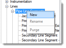
If you want to create a new Line (no difference between Pipe Lines and Signal Lines) you just need to create a new class.
After that you can click on the “Edit Line…” button to modify the Line properties.
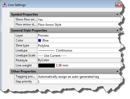
Under Symbol Properties you can define whether or not you want a Flow Arrow be placed automatically when drawing this Line.
Gap priority allows you to set a value between 1 and 9. 1 being the highest priority and 9 the lowest. This influences the way Lines are broken when crossing. The line with the higher priority won’t be broken.
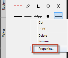
When you add a Line to the Tool Palette the Line will be shown as a simple black line. Make a Right-click on it and select “Properties…”.
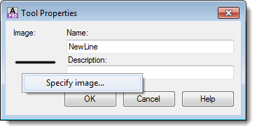
In the next Dialog you make a Right-Click on the image and select “Specify image…”. This allows you select an image file. The resolution of the image should be 32x32.
Creating Symbols
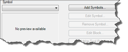
Creating Symbols works a little different than creating a Line. When you select a class which has no Symbol assigned to it yet only the “Add Symbols…” button is enabled.
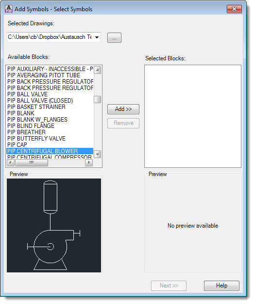
The first thing you do is select the drawing which contains the blocks you want to use for the Symbols. It isn’t mandatory that you use the projSymbolStyle.dwg. Maybe you have a drawing which contains all your blocks and you want to use this drawing.
If you have a bunch of blocks you want to integrate in your project it is recommended to add all those blocks into the projSymbolStyle.dwg. This just speeds up the process.
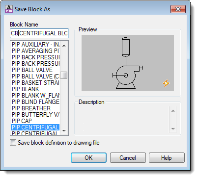
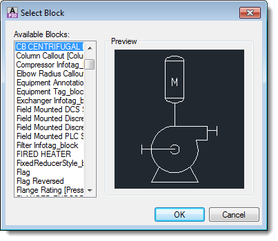
If you want to just create a new symbol and you don’t have a block yet, you select the projSymbolStyle.dwg (as shown in the picture below). Next you select a block which may or may not be close to the Symbol you want to create.
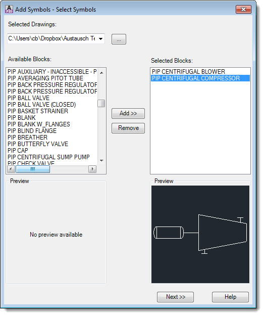
You can actually add multiple blocks to your selection.
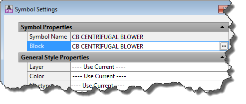
In the next dialog you now can set the various properties and assign the proper class as well.
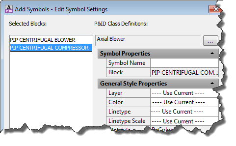
You have to type in a Symbol Name otherwise you will be asked to do so.
Now the block is assigned to our class, but we still need to change the block.

This procedure is needed only if you used a copy of an existing Symbol and we need to change the Symbol now. If you used a block of your own from your own source, you already assigned the proper block to the class.
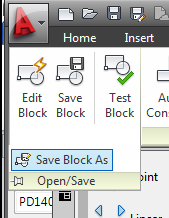
If we used a copy of a block we have to firstly save the block under a different name. For that we click on “Edit Block…” to open the Block Editor. The first thing you do is used “Save Block As” to save the block under a different name.
Type in a new block name.
Now you can make your modifications and then just close the Block Editor.
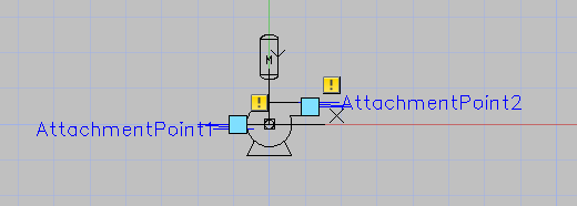
Tip: It is recommended to use BYLAYER for Color and Line Type and put the objects on Layer 0.
Now you have to assign the new block to your Symbol.
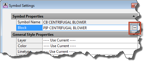
Again you select the projSymbolStyle.dwg of your Project and select your new block.
Now you are done. Last step is to add the Symbol to the Tool Palette.