Step 5: Create Tags and Annotations Creating Tags
The Tag is a unique identifier in a Project. The Tag has to be unique no matter what the class as well. For example you can’t have a Tag V101 for an Equipment and also V101 for a Hand Valve.
By default Tags can be defined for:
Equipment
Hand Valves
Piping Specialty Items
Pipe Line Segments
Signal Line Segments
Instrumentation
Nozzles
Pipe Line Groups
In general: Where ever there is a Tag property you can define Tag Formats. You can define multiple Tag Formats for one class also.
If you want to modify a Tag Format you select the Tag Format and click on Modify…
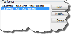
You can create a new Tag Format by using an existing one as a template. Again just select a Tag Format and this time click on New…
Next the Tag Format Setup dialog opens up. Here you can select first of all from how many sub-parts your Tag is made of. Using the German KKS System you have at least 5 – 6 sub-parts. Sometimes customization brings you up to 8 – 10, but often less is more. So don’t over do it just because you can.
Between each sub-part you can define a delimiter. If you don’t need on then just delete it.
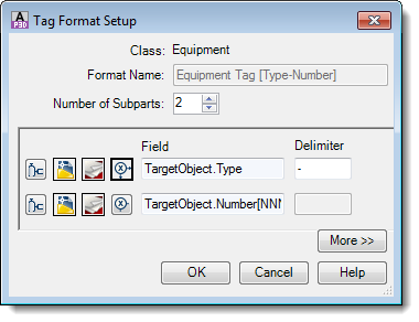
For each sub-part you have four button to chosse from where the data comes from.
 Selecting
from Class properties
Selecting
from Class properties
![]() Selecting
from Drawing properties
Selecting
from Drawing properties
![]() Selecting
from Project properties
Selecting
from Project properties
![]() Defining
expressions or using auto-generated values
Defining
expressions or using auto-generated values
If selecting Class properties you will be shown the properties of the class the Tag Format is for.
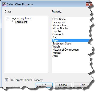
If you uncheck Use Target Object’s Property you will see all classes with all properties.
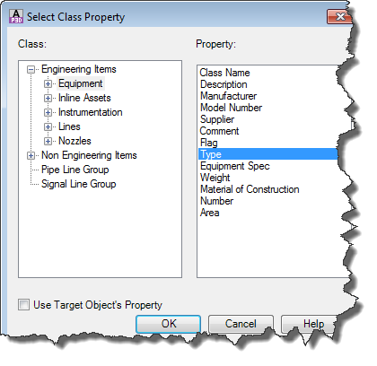
Even though you may have now all classes and properties at your disposal, you can select only those properties which are in a relationship with the class you are defining the Tag Format for. For example if defining the Tag for Equipment you can’t use properties of Hand Valves.
Again you may want to play a little bit to find out what works.
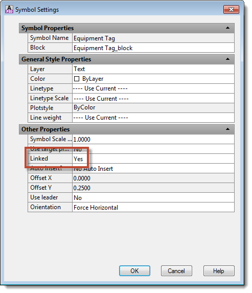
If you created a new Tag you have to assign the new Tag to your class. This is done at the TagFormatName property.
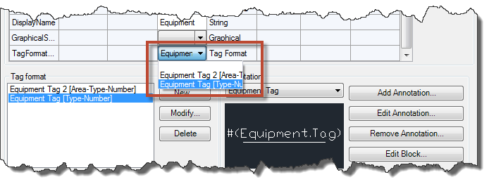
Creating a Tag Format for the Equipment class doesn’t mean that you have to assign this Tag for the Equipment class as well. Maybe your Tag Format is needed only for some specific Equipment (e.g. Mechanical Drivers). Then you select the Mechanical Drivers class and change the TagFormatName property there.
Creating Annotations & Labels
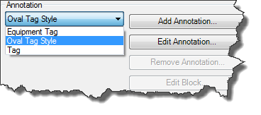
Crating Annotations is essentially no different than creating Tags. Again you can create as many Annotations as you want. It is also important that you be aware for which class you create a new Annotation. If you create an Annotation for a specific class the Annotation will be available for this class and all it’s sub-classes.
You can delete an Annotation or edit its Bock only at the class where the Annotation was created.
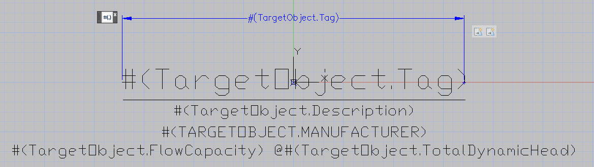
If you use “Edit Block” to make changes to an Annotation the Block Editor opens up and shows the Annotation and a one button Toolbox.
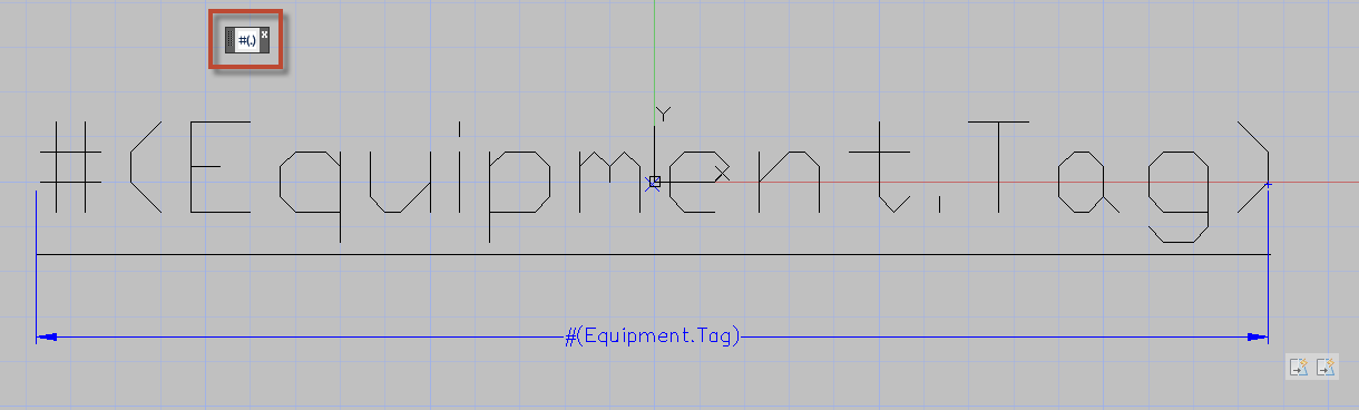
An Annotation is usually made out of Attributes and some Standard AutoCAD® Elements like Lines. If you need multiple Attributes you just copy the existing one and adapt the Attribute to your liking (Text Height, Text Style and so on).
Below you see an example for a Pump Info Tag.
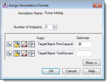
If you click on the button of the Toolbox you are asked to select an Attribute. Then a familiar dialog opens up.
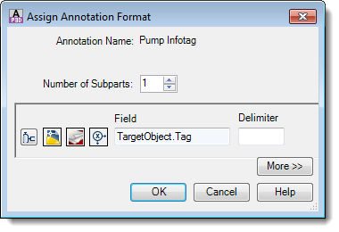
As with Tag Formats you can have multiple properties represented in one Attribute.
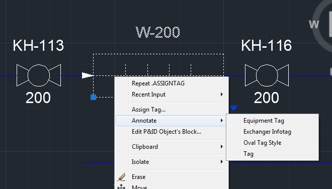
Tip: In the Assign Tag dialog you will see only those Annotations which have the property Tag in it. So if your Annotation is made out of single Properties and Tag is not among them it won’t show up here.
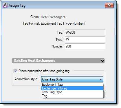
However, it will be listed at the context menu.
If you create an Annotation you maybe don’t want to move it with your symbol. It is supposed to stay where you positioned it. If this is the case you have to set the Annotation property to Linked = No.