

17. Main elements of use case diagram: definitions, description, examples.
Def: A use case diagram at its simplest is a representation of a user's interaction with the system and depicting the specifications of a use case. A use case diagram can portray the different types of users of a system and the various ways that they interact with the system.
Desc: Use case diagram lets you model system functions (i.e. goals) as well as the actors that interaction with those functions. Main elements:
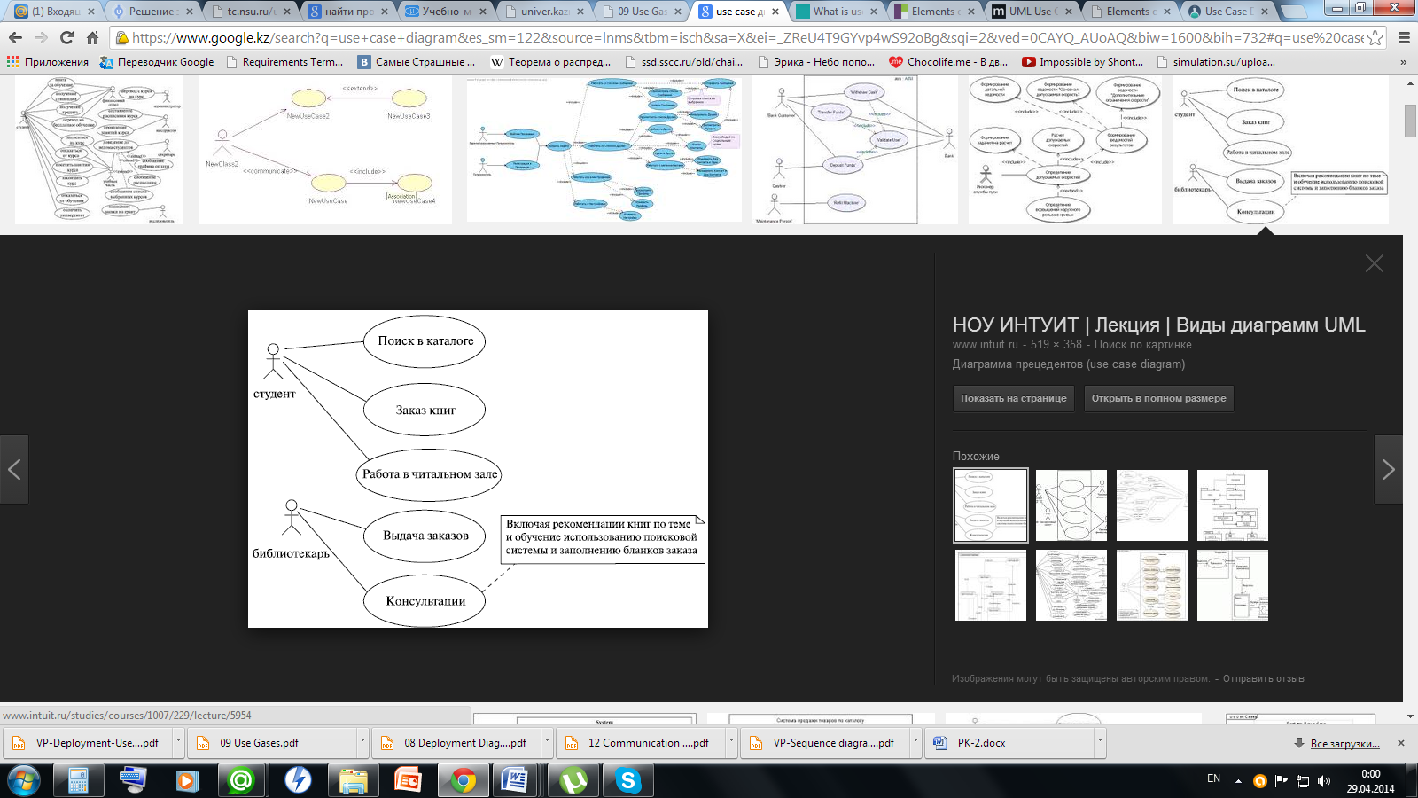
Actor: is a role that user plays with respect to the system. The different roles the actor represents are actual business roles of the users in a system. While modeling, it is up to the you to consider what actors make an impact on the functionality that you want to model. If the entity does not affect a certain piece of functionality that you are modeling, it makes no sense to represent it as an actor. An actor is shown as a stick figure in use case diagram depicted “outside” the system boundary
Use case: is a set of scenarios tied together by a common user goal. It Represents the actions performed by one or more actors in the pursuit of a particular goal. A use case is a kind of type.
System boundary: A system boundary defines the scope of what a system will be. A system cannot have infinite functionality. So, it follows that use cases also need to have definitive limits defined. A system boundary of a use case diagram defines the limits of the system. The system boundary is shown as a rectangle spanning all the use cases in the system.
An association is a connection between an actor and a use case. An association indicates that an actor can carry out a use case.
Use cases share different kinds of relationships:
- Include: When a use case is depicted as using the functionality of another use case in a diagram, this relationship between the use cases is named as an include relationship.
- Extend: In an extend relationship between two use cases, the child use case adds to the existing functionality and characteristics of the parent use case.
- Generalizations: A generalization relationship is also a parent-child relationship between use cases.
Ex:
18. Levels of use cases on use case diagram: definitions, description, examples.
Def: Use cases exist at different levels of granularity. Alistair Cockburn, leading authority on use cases, describes five levels of granularity, known as Cloud level, Kite level, Sea level, Fish level and Clam level.
Desc:
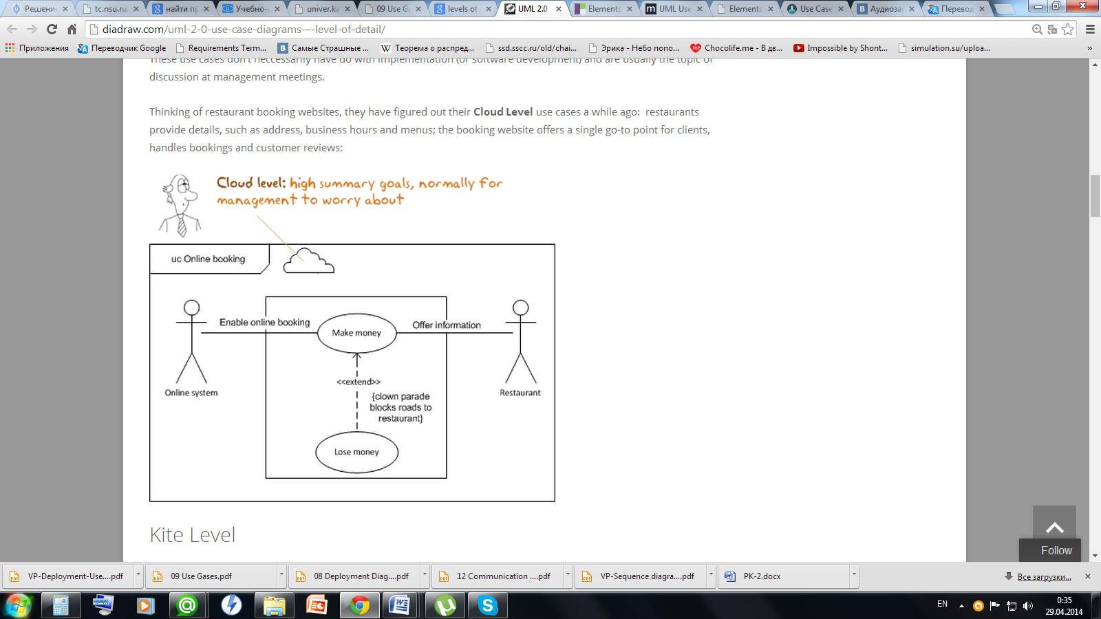
At Cloud Level a use case represents ways of getting to goals, that are highly summarised, such as as ‘make money’. These use cases don’t neccessarily have do with implementation (or software development) and are usually the topic of discussion at management meetings. Ex:
Kite Level
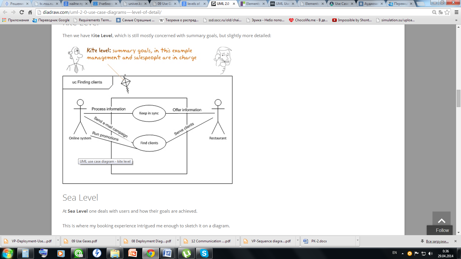
Then we have Kite Level, which is still mostly concerned with summary goals, but slightly more detailed. Kite-level use cases show how the sea-level use cases fit into wider business interactions. Kite-level use cases are usually business use cases, whereas sea and fish levels are system use cases. You should have most of your use cases at the sea level. Ex:
At Sea Level one deals with users and how their goals are achieved. The core use cases are at “sea level.” Sea-level use cases typically represent a discrete interaction between a primary actor and the system. Such use cases will deliver something of value to the primary actor and usually take from a couple of minutes to half an hour for the primary actor to complete.
Fish Level
:WE take a peak at the level, which is concerned with the implementation of the system, underlying the diagram at sea level/ Use cases that are there only because they are included by sea-level use cases are fish level.
At Clam Level we get into the nitty-gritty details.