

14. Main elements of package diagram: definitions, description, examples.
A package is a grouping construct that allows we take any construct in the UML and group its elements together into higher-level units. Its most common use is to group classes, and that's the way I'm describing it here, but also we can use packages for every other bit of the UML as well. In a UML model, each class is a member of a single package. Packages can also be members of other packages, so we are left with a hierarchic structure in which top-level packages get broken down into subpackages with their own subpackages and so on until the hierarchy bottoms out in classes. A package can contain both subpackages and classes.
Each package represents a namespace, which means that every class must have a unique name within its owning package. If I want to create a class called Date, and a Date class is already in the System package, I can have my Date class as long as I put it in a separate package. To make it clear which is which, I can use a fully qualified name, that is, a name that shows the owning package structure. Also We use double colons to show package names in UML, so the dates might be System::Date and MartinFowler::Util::Date.
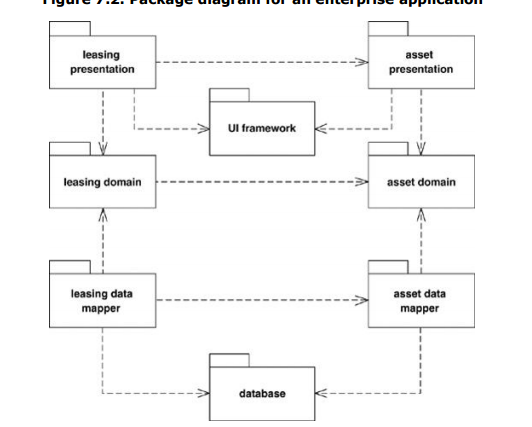
If we have packages for presentation and domain, we have a dependency from the presentation package to the domain package if any class in the presentation package has a dependency to any class in the domain package. In this way, interpackage dependencies summarize the dependencies between their contents.
15. How to show aspects on package diagram: definition, description, example.
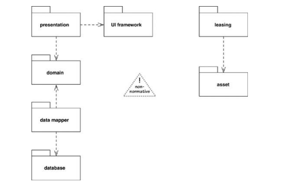
With this diagram, we can clearly see each aspect. However, these two aspects aren't true packages, because we can't assign classes to a single package. This problem mirrors the problem in the hierarchic namespaces in programming languages. Although diagrams like Figure are nonstandard UML, they are often very helpful in explaining the structure of a complex application.
16. Main elements of deployment diagram: definitions, description, examples.
Def: A deployment diagram in the Unified Modeling Language models the physical deployment of artifacts on nodes.Deployment diagrams show a system's physical layout, revealing which pieces of software run on what pieces of hardware. Deployment diagrams are really very simple. The main items on the diagram are nodes connected by communication paths. A node is something that can host some software. Nodes come in two forms. A device is hardware, it may be a computer or a simpler piece of hardware connected to a system. An execution environment is software that itself hosts or contains other software, examples are an operating system or a container process.
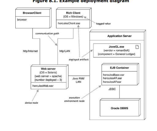
The nodes contain artifacts, which are the physical manifestations of software: usually, files. These files might be executables (such as .exe files, binaries, DLLs, JAR files, assemblies, or scripts), or data files, configuration files, HTML documents, and so on. Listing an artifact within a node shows that the artifact is deployed to that node in the running system. We can show artifacts either as class boxes or by listing the name within a node. If we show them as class boxes, we can add a document icon or the «artifact» keyword. We can tag nodes or artifacts with tagged values to indicate various interesting information about the node, such as vendor, operating system, location, or anything else that takes our fancy.
Often, we'll have multiple physical nodes carrying out the same logical task. We can either show this with multiple node boxes or state the number as a tagged value. In Figure, I used the tag number deployed to indicate three physical Web servers, but there's no standard tag for this. Artifacts are often the implementation of a component. To show this, we can use a tagged value in the artifact box. Communication paths between nodes indicate how things communicate. We can label these paths with information about the communication protocols that are used.