28. Collaborations: definition, description, example.
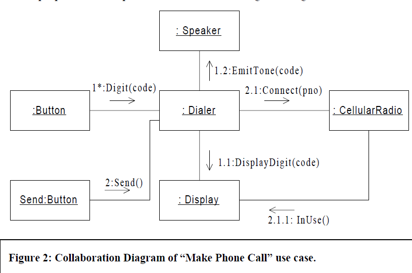
Def: UML Collaboration diagrams (interaction diagrams) illustrate the relationship and interaction between software objects. The collaboration diagram illustrates messages being sent between classes and objects (instances). A diagram is created for each system operation that relates to the current development cycle (iteration). When creating collaboration diagrams, patterns are used to justify relationships. Patterns are best principles for assigning responsibilities to objects and are described further in the section on patterns. There are two main types of patterns used for assigning responsibilities which are evaluative patterns and driving patterns.
In a collaboration, the naming scheme is participant-name/ role-name: class-name. As usual, all these elements are optional.
Descr: Collaborations do provide a way to group chunks of interaction behavior when roles are played by different classes.
Example:
29. Main elements of interaction overview diagram: definitions, description, examples.
Def: Interaction overview diagram is the variant of activity diagram. Interaction overview diagrams overview control flow. The main element, frame showsany type of interaction diagram.
Des: Interaction overview diagrams are very similar to activity diagrams. While activity diagrams shows a sequence of processes Interaction overview diagrams shows a sequence of interaction diagrams.
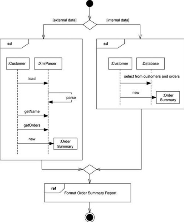
Interaction overview diagrams are a grafting together of activity diagrams and sequence diagrams. We can think of interaction overview diagrams either as activity diagrams in which the activities are replaced by little sequence diagrams, or as a sequence diagram broken up with activity diagram notation used to show control flow. Either way, they make a bit of an odd mixture.
Example. In this diagram, we want to produce and format an order summary report. If the customer is external, we get the information from XML; if internal, we get it from a database. Small sequence diagrams show the two alternatives. Once we get the data, we format the report; in this case, we don't show the sequence diagram but simply reference it with a reference interaction frame.
30. Main elements of timing diagram: definitions, description, examples.
Def: Timing diagram shows time, event, space and signal for real-time and distributed system
Descr: Timing diagrams are useful for showing timing constraints between state changes on different objects. The diagrams are particularly familiar to hardware engineers.
Duration Constraint: Is an interval constraint that refers to a duration interval.
Time constraint is shown as graphical association between a time interval and the construct that it constrains. Typically this graphical association is a small line, between an occurrence specification and time interval.
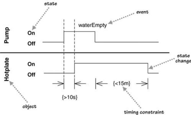
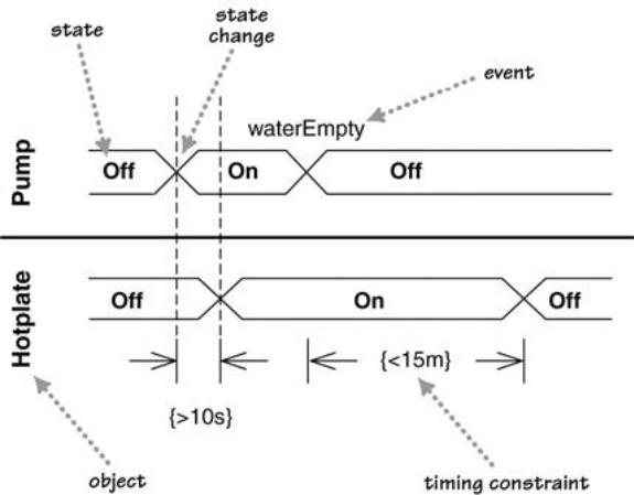
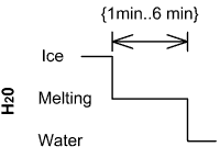
Figures 1 and 2 are alternative ways of showing these timing constraints. Both diagrams show the same basic information. The main difference is that Figure 1 shows the state changes by moving from one horizontal line to another, while Figure 2 retains the same horizontal position but shows state changes with a cross. The style of Figure 1 works better when there are just a few states, as in this case, and Figure 2 is better when there are many states to deal with.
Example: