

What is the uml?
The UML- family of graphical notations backed by single meta-model, that help in describing and designing software systems, particularly software systems using the object-oriented (OO) style. The Unified Modeling Language (UML) is a general-purpose modeling language in the field of software engineering, which is designed to provide a standard way to visualize the design of a system. It was created and developed by Grady Booch, Ivar Jacobson and James Rumbaugh at Rational Software in the 1990s.
The Unified Modeling Language (UML) is an open standard visual modeling language used for modeling businesses, software applications, and system architectures. Although the UML is a standard of the Object Management Group (OMG) the UML is not just for modeling object-oriented (OO) software applications. The UML is a graphical language that was designed to be very flexible and customizable. This enables we to create many different types of models, including models for understanding business processes, workflow, sequences of queries, applications, databases, architectures, and more.
The UML was born out of the unification of the many object-oriented graphical modeling languages that thrived in the late 1980s and early 1990s. It was created and developed by Grady Booch, Ivar Jacobson and James Rumbaugh at Rational Software in the 1990s. In 1997 it was adopted by the Object Management Group (OMG), and has been managed by this organization ever since. In 2000 the Unified Modeling Language was accepted by the International Organization for Standardization (ISO) as an approved standard. Since then it has been revised to cover the latest revision of UML.
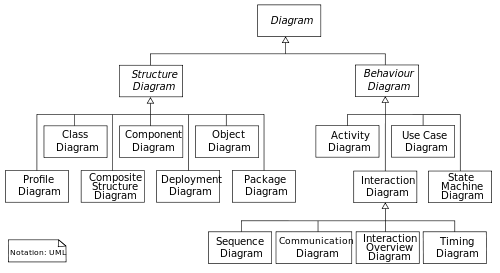
The Unified Modeling Language (UML) offers a way to visualize a system's architectural blueprints in a diagram (see image), including elements such as
Any activities (jobs)
Individual components of the system
And how they can interact with other software components.
How the system will run
How entities interact with others (components and interfaces)
External user interface
How the system is expected to be used.
Although originally intended solely for object-oriented design documentation, the Unified Modeling Language (UML) has been extended to cover a larger set of design documentation (as listed above) and been found useful in many contexts.
2. What are ways of using uml
There are 3 modes in which people use the UML: sketch, blueprint, and programming language. The most common of the three is UML as sketch. In this usage, developers use the UML to help communicate some aspects of a system. As with blueprints, we can use sketches in a forward-engineering or reverse-engineering direction. Forward engineering draws a UML diagram before we write a code, while reverse-engineering builds a UML diagram from existing code I order to help understand it. Sketches are also useful in documents, in which case the focus is communication rather than completeness. In contrast, UML as blueprint is about completeness. In forward engineering, the idea is that blueprints are developed by a designer whose job is to build a detailed design for a programmer to code up. In reverse engineering, blueprints aim to convey detailed information about the code either in paper documents or as an interactive graphical browser. The blueprints can show every detail about a class in a graphical form that’s easier for developers to understand. Blueprints require much more sophisticated tools than sketches do in order to handle the details required for the task. Specialized CASE-tools(computer-aided software engineering) as an example. Forward-engineering tools support diagram drawing and back it up with a repository to hold the information. Reverse-engineering tools read source-code and interpret from it into the repository and generate diagrams. Tools that can do both forward and reverse engineering like this are referred to as round-trip tools. Some tools use the source code itself as the repository and use diagrams as a graphic viewport on the code. These tools are called as tripless tools. As we do more and more in the UML and the programming gets increasingly mechanical, it becomes obvious that the programming should be automated. Indeed, many CASE tools do some form of code generation, which automates building a significant part of a system. Eventually, however, we reach the point at which all the system can be specified in the UML, and we reach UML as programming language. In this environment, developers draw UML diagrams that are compiled directly to executable code, and the UML becomes the source code. Obviously, this usage of UML demands particularly sophisticated tooling. (Also, the notions of forward and reverse engineering don't make any sense for this mode, as the UML and source code are the same thing.)