

1 Manufacturing
Manufacturing includes making anything from individual components or printed circuit boards to complete pieces of equipment such as televisions. In the case of the latter, it is usual to break down the equipment into modules and manufacture these separately. For 5 instance, television sets are manufactured in this way with each set consisting of up to seven individual modules. When the modules come off the assembly line, they are passed to groups of testers and troubleshooters to check for faults. The various modules are then assembled to produce the complete unit. The disadvantage of this 10 kind of work is the monotony and the time pressure of assembly line work.
2 Planning
Firms with large communications networks require planners. For instance, telecommunications network providers need to know where to place exchanges for maximum switching capability, and microwave 15 towers for minimum interference. They also need to know the sizes of cables to handle traffic growth.
Rapidly springing up everywhere from a number of different suppliers are the radio mobile, cellular, and paging networks. All these require careful planning and field surveys to prevent mutual interference. Job 20 opportunities will grow in this sector.
3 Installation
There is a wide range of installation work required, for example, installing exchanges, LANs, and medical equipment. Such work involves cabling and may require some knowledge of mechanical engineering if special racks and even entire rooms have to be 25 constructed to accommodate equipment. Installation work usually involves travel which can be overseas depending on the product involved.
4 Commissioning
Once equipment is installed, it needs to be commissioned, i.e. put into operation. Problems often emerge at this stage which have to be 30 ironed out. This work is usually done by engineers with long experience in the type of equipment being commissioned.
Student В
Speaking practice
Unit 1
Notes
RV1 Q2 is 2N 3053 (NPN)

Unit 5
Cell Mercury Lithium
Type |
primary |
|
Output voltage |
? |
3V |
Applications |
cameras, hearing aids, watches, ? |
photographic equipment |
Usual size |
button |
button and ? |
Advantages |
? but high energy |
long storage life, high voltages, last for long periods at low currents |
Disadvantages |
expensive |
? used cells should be disposed of carefully |
Task 5
В
oscillator
transmitter
power
amplifier
the
signal is radiated
![]()
If a target is hit. .
receiver
receiving antenna
radio frequency amplifier
CO
с
'w
ш о с
CD i_
0) ч—
ш
the signal is rectified
comparator
both signals are displayed
Unit 9
Task 7 Find out from your partner how to:
measure the voltage drop across R2 in this circuit.
check the value of this resistor.
R1
R2
This information should help you to advise on your partner's problems.
R1
Ш
R2
Task 6
Frequency band
Some uses
Very low (VLF) ?
Low (LF) 30kHz-300kHz
? (MF)
300kHz-3MHz
High (HF)
Very high (VHF) 30MHz-?
Ultra high (UHF) 300MHz-3GHz
? (SHF)
(microwaves) above 3 GHz
communication with submarines
? and
communication over large distances
medium wave, local and distant radio
short wave radio and communication, amateur and CB radio
? , police,
meteorology devices
TV (bands 4 and 5) and
?
? , communication
satellites, telephone and TV links
Unit 13
Task 6 Find out from your partner the missing values in these amplifier specifications.
Ask him or her to explain items 1-3. Explain to your partner with the help of the passage below what items 4-7 mean. Your partner also has Figs. 1 and 2.
voltage gain ?
frequency response ?
distortion ?
S/N ratio greater than 6 5dB
input impedance 50 kilohm
output impedance 600 ohm
supply voltage +9V to + 12V
Amplifiers
Amplifiers are used in almost all electronic circuits. In audio systems, the very small signal voltages produced by microphones, tape recording heads, magnetic pickup heads, etc. are amplified by a pre-amp. A power amp is then used to enable the signals to drive a 5 loudspeaker.
Any unwanted signals in an amplifier are known as noise. Unfortunately, noise is randomly produced inside most circuit components such as resistors, capacitors and semi-conductors. This type of noise is amplified and heard through the loudspeakers as hiss 10 and crackle. Noise is also induced by the low frequency mains supply. This may be heard through the loudspeaker as hum. The ratio of noise to signal power is known as the S/N (signal-to-noise) ratio and is
normally expressed in dB. For hi-fi sound reproduction, the S/N ratio must have a value greater than 70dB. Tape cassette recorders can only 15 achieve this S/N level by using special noise reduction systems such as Dolby or Dbx.
mid-band
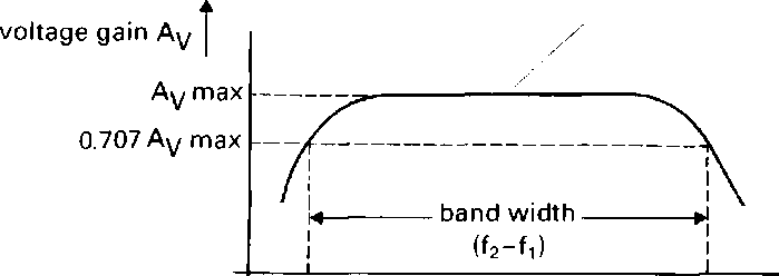
upper cut-off frequency f2
lower cut-off frequency -frequency fi
To prevent voltage and power loss, the input and output impedance of an amplifier must be matched to the other parts of the system. These impedances are measured in ohms. For minimum voltage loss, an 20 amplifier's input impedance should be high and its output impedance should be low.
Fig. 7.

Fig. 2.
Unit 16
Task 6 One recent recording system is a magneto-optical system called the MiniDisc
(MD) produced by Sony. It uses a combination of a laser and a magnetic field to read and write data on plastic discs almost half the size of a CD. One advantage of this system over digital tape is that it gives random access to individual tracks rather than serial access, i.e. it can immediately jump to any part of the recording rather than having to play from the beginning to the end.
In the MD system, as in CD systems, the sound is sampled at 41.1kHz but the data is compressed by 20% to give a 74-minute recording capacity. Because of the low power requirement of the laser, the system can be operated from a battery, making it compact and portable. It is also shock-proof. The MiniDisc can be re-recorded and, as with other digital systems, there is almost no quality loss when discs are copied.
Describe this graph in sufficient detail for your partner to sketch it. If you have problems, the text which follows may help you.

Use this matrix to help you sketch your partner's graph.
/p/mA 80-
60-
40-
20-0
-100
l
-50
~02 0Л Об 0.8 VF/V
/я/ц,А
Symptom |
Cause |
Remedy |
Power doesn't turn on. |
? |
p |
|
Timer is set to ON. |
Set Timer to OFF. |
Power is on but unit doesn't operate. |
? |
? |
TV programmes cannot be recorded. |
Aerial lead is not connected. |
Connect aerial lead correctly. |
Timer recording doesn't work. |
Recording start or stop time setting is incorrect. |
Set recording start and stop time correctly. ? Adjust clock to present time. ? |
|
Clock shows incorrect time. ? |
|
Playback picture is not in colour. Playback picture has large amounts of 'snow'. |
Reception channel was not adjusted correctly during recording. p |
Readjust reception channel. ? |
|
? Tape is old and/or defective. |
Consult qualified service personnel. ? |