

20 With an oscilloscope so that a visual display of the waveform can be seen.
Reading
Information
transfer
The
task which follows provides further practice in combining
information from a diagram and a text when reading.
Task
5 With
the help of this diagram, complete the gaps in the text.
first
accelerating anode A1
Aquadag
coating
phosphor
coating on inner side of screen
focusing
anode A2
cathode
С
pins
for electrical connections
heater
filament
electron
gun section: cathode plus intensity and focusing system
deflection
system
(electrostatic)
CRT
construction
Fig.
7
Cathode
ray tube
Televisions
as well as computers, radar systems, and oscilloscopes use a cathode
ray tube (CRT) to produce an output display. The construction and
operation of the CRT is similar in each case but the simplest type
of CRT is found in oscilloscopes.
A
CRT is really a large vacuum tube valve. It has 1 main
sections.
The
first section is an electron which emits a stream of electrons.
The
electron gun contains an electron lens which 3 the
electrons
into
a narrow electron *
The
second section is a! system,
which allows the beam to be
moved
t or
horizontally. Oscilloscopes use charged metal
I to
give8 deflection,
whereas television sets use
electromagnetic
coils to give electromagnetic
The
last section is a screen with a - coating.
The electron beam
hits
the screen, making the phosphor glow and causing a spot to be
displayed. The colour of the spot depends on the type of phosphor
used.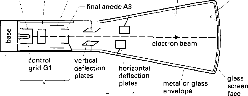
Language study Cause and effect, 2
Study these statements:
The electron beam hits the screen.
The phosphor glows.
Why does the phosphor glow? What is the relationship between statement (1) and (2)?
Statement (1) is a cause and statement (2) is an effect. We can link cause and effect statements in a number of ways. Study these ways, which use cause and make.
The electron beam hits the screen causing the phosphor to glow. The electron beam hits the screen making the phosphor glow. Now study these cause and effect statements:
The phosphor glows.
A spot is displayed.
The effect is in the passive. We can link cause and effect like this: The phosphor glows causing a spot to be displayed.
Link each of these cause and effect statements to make one sentence:
a A magnetic field is set up in the speaker coil,
b The coil vibrates.
a The coil pushes and pulls the speaker cone,
b Sound waves are produced.
a A voltage is applied to a quartz crystal, b The quartz crystal expands and contracts.
a A voltage is applied to the Y-plates. b The electron beam is deflected.
a Current flows through the filament, b The heater glows.
Word Study Compound nouns, 2
Study these examples of compound nouns:
a signal generator = equipment for generating signals a cassette player = equipment for playing cassettes a battery tester = equipment for testing batteries
What do we call equipment for ... playing CDs? receiving radio (signals)? charging batteries? amplifying aerial (signals)? filtering (out) noise? synthesizing speech? cleaning cassette heads? amplifying (the) power (of a signal)? sensing vibration?
scanning (the human) body (for disease)?
Technical reading Cathode ray oscilloscope
Task 8 Work in groups of three: A, B, and C.
Student A: Read Electron gun and take notes. Student B: Read Deflection system and take notes. Student C: Read Phosphor screen and take notes.
Using your notes and Fig. 1 on page 104, explain to the others in your group how your section of the CRT works. A should start. В may use Fig. 2 as part of the explanation.
Electron gun para
A stream of electrons is released from the surface of the cathode (C) 1 when it is heated by the heater filament. The electrons are accelerated towards the screen by a set of three positively-charged cylindrical anodes (A1, A2, A3). Each anode has a higher charge 5 than the one before. As the electrons move towards the anodes, they pass through a hole in a negatively-charged metal disc. This disc is known as the control grid. By adjusting the intensity control on the oscilloscope, the charge on the grid can be varied. This allows the number of electrons reaching the screen, and therefore io the brilliance or brightness of the spot on the screen, to be adjusted.
The three anodes form the electron lens. The oscilloscope focus 2 control allows the ydltage on the second anode (A2) to be varied and causes the stream of electrons to be focused into a narrow beam. If the oscilloscope has an astigmatism control, it is used to 15 vary the voltage an the third anode (A3). This allows the shape of the spot on the screen to be adjusted to make it perfectly round.
Deflection system
After leaving the electron gun, the electron beam is deflected by з two pairs of parallel metal plates. The pairs of deflection plates are situated at right angles to each other.
20 The signal to be measured is amplified by the Y-amplifier in the 4 oscilloscope, then applied to the first set of deflection plates, known as the Y-plates. This causes the electron beam to be deflected vertically in proportion to^he magnitude of the input signal.
The oscilloscope has a timebase generator which produces a 5
25 sawtooth wave output as shown in Fig. 2.

para
This is fed into the X-amplifier of the oscilloscope, then applied to 6 the second set of deflection plates, known as the X-plates. This causes the electron beam to be deflected in the horizontal direction in such a way that the spot moves from left to right across the 30 screen at a steady rate. When it reaches the right side of the screen, it rapidly returns to the left side again. This allows the screen to show how the measured signal varies with time.
Phosphor screen
The X and Y deflections of the electron beam cause the signal being 7 measured to be displayed in the form of a wave, with the 35 magnitude of the signal being given on the vertical axis and the time variation on the horizontal axis. A piece of transparent plastic known as a graticule is attached to the front of the screen. This has a grid of horizontal and vertical lines marked on it and allows accurate measurements of the signal to be made.
40 A large build-up of negative charge could be caused by the electron 8 beam hitting the phosphor screen. To help prevent this, the inside of the CRT, between the deflection system and the screen, is coated with a carbon compound known as Aquadag. This is attached to the high voltage anode (A3) to provide an escape path for the excess