- •Section 2. Aerodynamics of bodys of revolution Theme 12. The aerodynamic characteristics of Bodys of revolution, fuselages and their analysis
- •12.1. Lifting force of a body of revolution.
- •12.1.1. Lift of a nose part.
- •12.1.2. Lift of the cylindrical part.
- •12.1.3. Lift of the rear part.
- •12.2. Aerodynamic moment of a body of revolution. Coordinate of aerodynamic center.
- •12.2.1. Aerodynamic moment of a nose and coordinate of an aerodynamic center.
- •12.2.2. Coordinate of the aerodynamic center of the cylindrical part.
- •12.2.3. Coordinate of the aerodynamic center of the rear part.
- •12.2.4. Coordinate of the aerodynamic center of body of revolution in a whole.
Section 2. Aerodynamics of bodys of revolution Theme 12. The aerodynamic characteristics of Bodys of revolution, fuselages and their analysis
12.1. Lifting force of a body of revolution.
According to the theory of an elongated body the factor of pressure on surface of a body of revolution at flow about it at an angle of attack is determined by the formula
![]() ,
(12.1)
,
(12.1)
where
 .
.
With taking that into account for a lift coefficient (11.9) it is obtained1
 .
.
Let's consider distribution of a lift coefficient along length of a body of revolution
![]() ,
(12.2)
,
(12.2)
where
![]() - cross-sectional area of a body of revolution.
- cross-sectional area of a body of revolution.
The last formula is more general and fair for any shapes of cross sections.
From
obtained expression follows, that on a fuselage lift occurs only on
sites with the variable area of cross sections
![]() ,
at that, the sign of lift is determined by the sign of derivative
,
at that, the sign of lift is determined by the sign of derivative
![]() .
Therefore, on extending nose part positive lifting force occurs,
since here
.
Therefore, on extending nose part positive lifting force occurs,
since here
![]() ,
on the tapering rear part - negative lift, and on the cylindrical
part lift will be absent.
,
on the tapering rear part - negative lift, and on the cylindrical
part lift will be absent.
Experiments
and more precise calculations show, that the above mentioned
qualitative analysis remain fair and for not thin fuselages. The
quantitative results according to this theory are satisfactory only
for nose and cylindrical parts at
![]() .
For the rear part the theory does not take into account the influence
of a boundary layer and flow stall, due to this influence the
absolute value of lifting force decreases. At supersonic speeds (
.
For the rear part the theory does not take into account the influence
of a boundary layer and flow stall, due to this influence the
absolute value of lifting force decreases. At supersonic speeds (![]() )
the theory does not take into account influence of nose shape and
numbers
)
the theory does not take into account influence of nose shape and
numbers
![]() ,
for cylindrical part - occurrence of lift due to “carry” from the
nose part.
,
for cylindrical part - occurrence of lift due to “carry” from the
nose part.
The lift
coefficient
![]() of a body of revolution can be presented as a sum of the factors of
lifts of its parts. The lift coefficient is calculated separately for
nose, cylindrical and rear parts. For thin fuselages close to body of
revolutions, the calculation should be performed having used the
theory of an elongated body with consequent refinement of influence
of the various factors which are not taken into account by this
theory.
of a body of revolution can be presented as a sum of the factors of
lifts of its parts. The lift coefficient is calculated separately for
nose, cylindrical and rear parts. For thin fuselages close to body of
revolutions, the calculation should be performed having used the
theory of an elongated body with consequent refinement of influence
of the various factors which are not taken into account by this
theory.
So, generally it is possible to write down for the fuselage lift coefficient
![]() ,
,
where ![]() .
(12.3)
.
(12.3)
The size of
the derivative
![]() depends on the shape of the body of revolution and first of all from
its nose part, angle of attack
depends on the shape of the body of revolution and first of all from
its nose part, angle of attack
![]() ,
structure of a boundary layer, number
,
structure of a boundary layer, number
![]() and other factors.
and other factors.
12.1.1. Lift of a nose part.
In
accordance to the theory the lifting force is distributed according
to the law
![]() in subsonic range of speeds (
in subsonic range of speeds (![]() ).
From here
).
From here
 ;
;
![]() ,
,
 .
(12.4)
At absence
of the air intake in the nose part (![]() )
)
![]() .
.
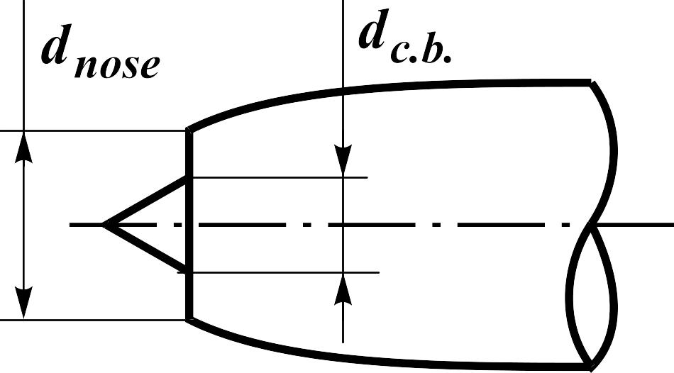
It has to
be noted, that at working engine, when air is sucked through the air
intake, an additional air intake lift occurs which should be taken
into account in
![]() .
.
Approximately this force can be estimated by the formula
![]() ,
(12.5)
,
(12.5)
Fig.
12.1.
![]() - relative area of the body central part in input cross-section of
the air intake (
- relative area of the body central part in input cross-section of
the air intake (![]() )
(Fig. 12.1),
)
(Fig. 12.1),
![]() - flow coefficient of air flow rate (on computational operational
mode of the air intake
- flow coefficient of air flow rate (on computational operational
mode of the air intake
![]() ).
).
The value
of a derivative
of the lift coefficient of the air intake
![]() is added to a derivative of the nose part.
is added to a derivative of the nose part.
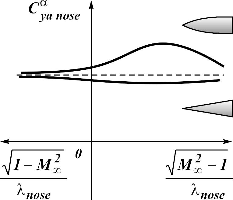
At
supersonic speeds of flight the size of the derivative
depends on the shape of the nose part and aspect ratio (parameter
![]() )
(Fig. 12.2).
)
(Fig. 12.2).

Fig. 12.2. Influence of the shape of the nose part onto the derivative
Examples:
- conical nose part without the air intake (w/o a.i.)
![]() ;
(12.6)
;
(12.6)
- shape of the nose part with curvilinear generative line without the air intake (w/o a.i.)
![]() ;
(12.7)
;
(12.7)
- at presence of the air intake
 ,
(12.8)
where .
