

Main Features of UWB Radars and Differences from Common Narrowband Radars
Igor I. Immoreev
CONTENTS
Introduction
Information Possibilities of UWB Radars
How UWB Radar Differs from Conventional Radar
Moving Target Selection in the UWB Radar and Passive Jamming Protection
Short Video Pulse Features in UWB Radar
References
1.1 INTRODUCTION
The majority of traditional radio systems use a narrow band of signal frequencies modulating a sinusoidal carrier signal. The reason is simple: a sine wave is the oscillation of an LC circuit, which is the most elementary and most widespread oscillatory system. The resonant properties of this system allow an easy frequency selection of necessary signals. Therefore, frequency selection is the basic way of information channel division in radio engineering, and the majority of radio systems have a band of frequencies that is much lower than their carrier signal. The theory and practice of modern radio engineering are based on this feature.
Narrowband signals limit the information capability of radio systems, because the amount of the information transmitted in a unit of time is proportional to this band. Increasing the system's information capacity requires expanding its band of frequencies. The only alternative is to increase the information transmitting time.
This information problem is especially important for radiolocation systems, where the surveillance time of the target is limited. Past radars have used a band of frequencies that does not exceed 10 percent of the carrier frequency. Therefore, they have practically exhausted the information opportunities in terms of range resolution and target characteristics. A new radar development is the transition to signals with a wide and ultra-wide bandwidths (UWBs).
For designing UWB radars, as with any other equipment, we must understand the required theory that will allow us to correctly design and specify their characteristics. The theory is also necessary for defining the requirements of radars and for developing the equipment needed to create, radiate, receive, and process UWB signals. In spite of recent developments and experimental work, there is no satisfactory and systematized theory of UWB radars available. The reason is that the process of radar-tracking and surveillance with UWB signals differs considerably from similar processes when using traditional narrowband signals. The study of these differences helps us to
understand when the traditional theory of radar-tracking detection can and cannot be used for
designing UWB radars. When traditional theory cannot be used, then we must develop new methods.
In this chapter, we will examine the new information opportunities that result from applying
UWB signals in radars, and the basic differences between UWB radars and narrowband radar
systems.
1.2 INFORMATION POSSIBILITIES OF UWB RADARS
The informational content of the UWB radars increases because of the smaller pulse volume of the signal. For example, when the length of a sounding pulse changes from 1 us to 1 ns, the depth of the pulse volume decreases from 300 m to 30 cm. We can say that the radar instrument probing the surveillance space becomes finer and more sensitive. The UWB radar's reduced signal length can
Improve detected target range measurement accuracy. This results in the improvement of the radar resolution for all coordinates, since the resolution of targets by one coordinate does not require their resolution by other coordinates.
Identify target classes and types, because the received signal carries the information not only about the target as a whole but also about its separate elements.
Reduce the radar effects of passive interference from rain, mist, aerosols, metallized strips, etc. This is because the scattering cross section of interference source within a small pulse volume is reduced relative to the target scattering cross section.
Improve stability when observing targets at low elevation angles at the expense of eliminating the interference gaps in the antenna pattern. This is because the main signal, and any ground return signal, arrive at the antenna at different times, which thus enables their selection.
Increase the probability of target detection and improved stability observing a target at the expense of elimination of the lobe structure of the secondary-radiation pattern of irradiated targets, since oscillations reflected from the individual parts of the target do not interfere and cancel, which provides a more uniform radar cross section.
Provide a narrow antenna pattern by changing the radiated signal characteristics.
Improve the radar's immunity to external narrowband electromagnetic radiation effects and noise.
Decrease the radar "dead zone."
Increase the radar's secretiveness by using a signal that will be hard to detect.
1.3 HOW UWB RADAR DIFFERS FROM CONVENTIONAL RADAR
1.3.1 Signal Waveform Changes during Detection and Ranging Processes
Narrowband signals (i.e., sinusoidal and quasi-sinusoidal signals) have the unique property of keeping their sinusoidal shape during forms of signal conversions such as addition, subtraction, differentiation and integration. The waveforms of sinusoidal and quasi-sinusoidal signals keep a shape identical to that of the original function and may differ only in their amplitude and time shift, or phase. Hereinafter, shape is understood as the law of change of a signal in time. On the contrary, the ultra-wideband signal has a nonsinusoidal waveform that can change shape while processing the above specified and other transformations.
Let us assume that a UWB signal St shown in Figure l.l is generated and transmitted to the antenna in a form of a current pulse. The first change of the UWB signal shape S2 occurs during
pulse radiation, since the intensity of radiated electromagnetic field varies proportionally with the derivative of the antenna current.
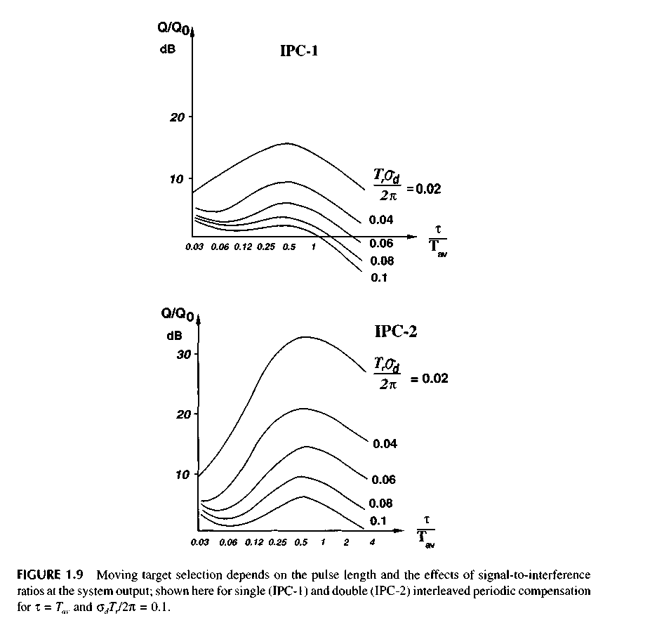
The second change of the shape occurs when pulse duration in the space ex (where с is velocity of light, X is the pulse duration in the time domain) is less than linear size of the radiator /. When current changes move along the radiator, then electromagnetic pulses are emitted from radiator discontinuities. As a result, a single pulse transforms into a sequence of к pulses divided by time intervals x, ,xk-1, shown as S3 in Figure 1.1. The apparent radiator length changes according to variations of the angle 9 between the normal to the antenna array and the direction of the wave front. Therefore, interpulse intervals vary with this angle as follows:
![]()
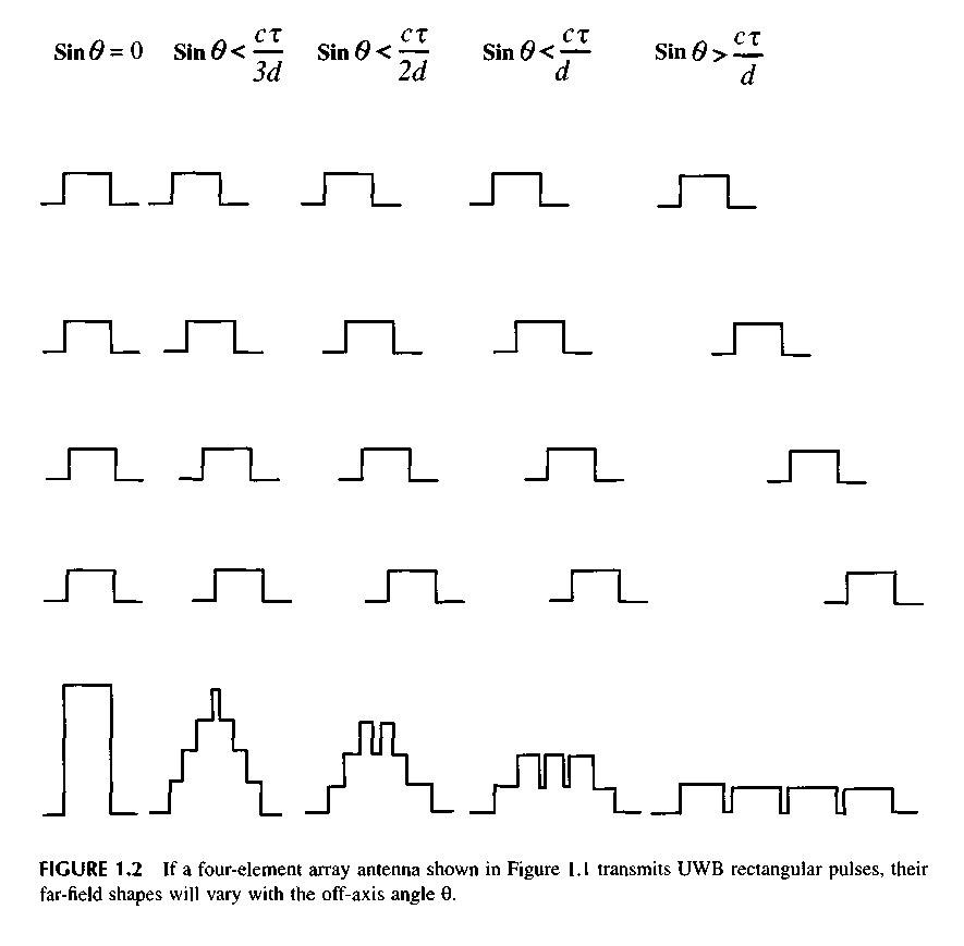
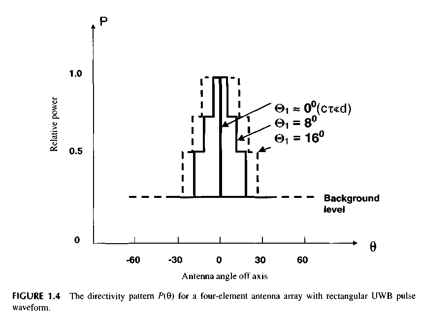
The third change of the shape occurs when the signal is radiated by a multi-element antenna array composed of N radiators with a distance d between them. The pulse radiated by one antenna element at the angle 9 is delayed by the time (d/c) sin 9 compared to the pulse radiated by the adjacent antenna element. The combined pulse will have various shapes and duration at different angles 9 in the far field as equation S4 in Figure 1.1. Far-field pulse shapes at different angles 9 are shown in Figure 1.2. Note that the combination of multiple square pulses radiated by the four-element antenna array and shifted in time over different angles have waveforms very different from the radiated rectangular video pulse.
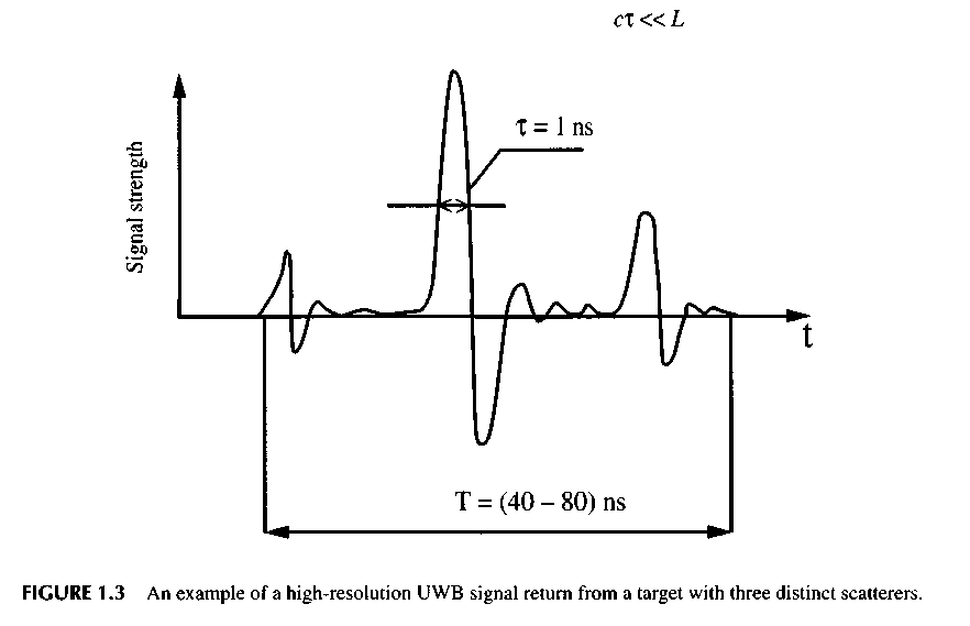
The fourth waveform change is S5 in Figure 1.1, and it occurs when the target scatters the signal. In this case, the target consists of M local scattering elements, or bright points, located along the line L. If the UWB signal length is сx « L, then the each discrete target element reflects the
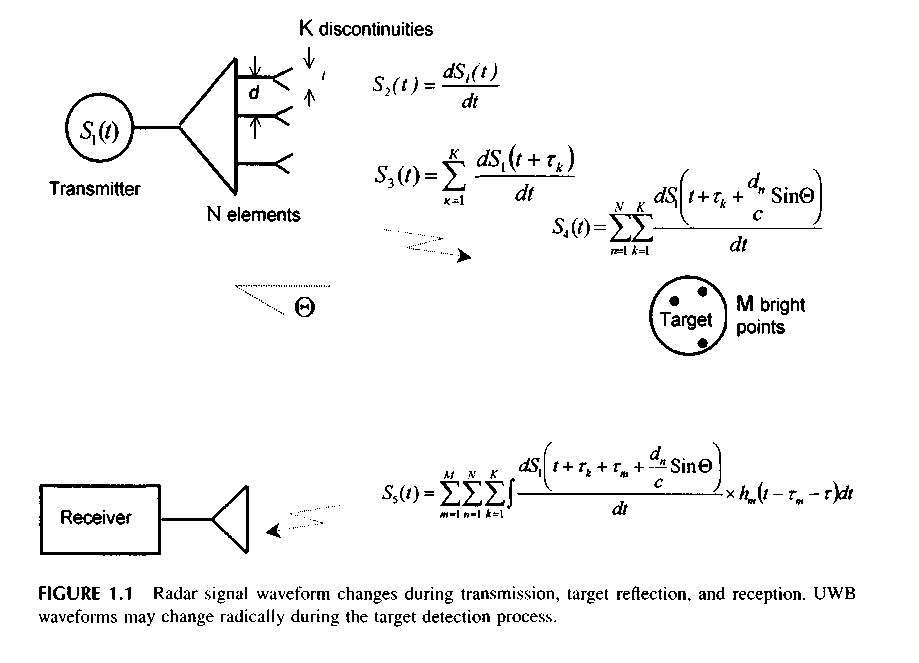
signal and forms a pulse sequence of M pulses. The actual number of pulses, time delay xm, and intensity depend on target shape and target element pulse response hm. This pulse sequence is called the target image. The whole image represents the time distribution of scattered energy that was formed during time interval t0 = 2L/c.
So, for the high-resolution UWB target case, the radar cross section (RCS) becomes time-dependent, and now we must introduce the concept of an instantaneous target RCS. The image will change with viewing angle variations. In this case, the target secondary pattern is nonstationary and variable. Because target scattered signals will form no secondary pattern "nulls," this promotes steady target viewing.
Some target elements may have a frequency bandwidth that is out of the UWB signal spectrum, so these will act as frequency filters and change the shape even more. Note that, in this case, the radar return signal not only indicates the presence of the target but carries back much information regarding the target. If the target were smaller than the radar pulse length ex, then no such information would be available.
The fifth change occurs during signal propagation through the atmosphere because of different signal attenuation in various frequency bands.
The sixth change of the shape occurs during signal reception. The reason for this is the same as for radiation, i.e., the time shift between current pulses induced by the electromagnetic field in the antenna elements located at various distances to the target. Figure 1.3 shows an example of an actual UWB signal reflected from a target with multiple scattering centers.
Following this discussion, we conclude that the UWB signal shape changes many times during radar viewing. It is difficult to describe such signals analytically. Conventional optimal processing using matched filters or correlators is unsuitable for these signals because of the changing waveform. Therefore, one of the most important problems with UWB radar is the development of signal processing methods that maximize signal-to-noise ratio when we perform the detection of the UWB signals.
1.3.2 How the UWB Signal Waveform and the Antenna Characteristics Mutually Affect Each Other
In Figure l .2, we can see as the waveform of the UWB signal changes depending on the off-axis angle. For the example of a rectangular pulse, the off-axis signals have the same energy but are changed in waveform to have a longer duration and less peak power. It is quickly apparent that our traditional concept of a single-frequency antenna directional pattern (DP) of the field no longer applies to UWB signals. The antenna directional pattern for UWB signals is measured for either peak or average power. This DP is formed only during radiation, which means that a UWB pattern is an instantaneous antenna pattern.
Let us consider DP for the peak power P(Q, ф) for the N radiating element antenna array. For an example, we will take one main cross section of this DP, F(0). Let us assume that the field video
pulse radiated by a single radiator of the array has a rectangular waveform, the duration T, and a peak power Pt. It is clear that the video pulses going from all radiators along the normal will arrive simultaneously at a receiving point. The peak power value at this point is Pmux = W,.
As the angle 6 increases, the time delay between video pulses is increasing. At an angle 8,, when sin 0, = ct/(N - \)d, the peak power falls by jump in size P, = (l/N) PmaK and becomes equal to (1 - 1 IN)Pmax. When sin 0 = sinQ2 = cx(N - 2)d, then the peak power falls once more for (1 IN)Pmax and becomes equal to (1 - 2/N)Pmax. So long as there is some angle 0^,, then the level of peak power will achieve the minimal value (l/N)Pmax = P,, which will be the background DP level. Thus, at the rectangular form of a radiating pulse DP, there is a step function as follows:
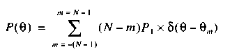
where 5(0) for a single pulse is
![]()
These DP P(0) is actually a multiplier of the array. To get the antennas complete DP, we must also consider the single radiator's directional pattern.
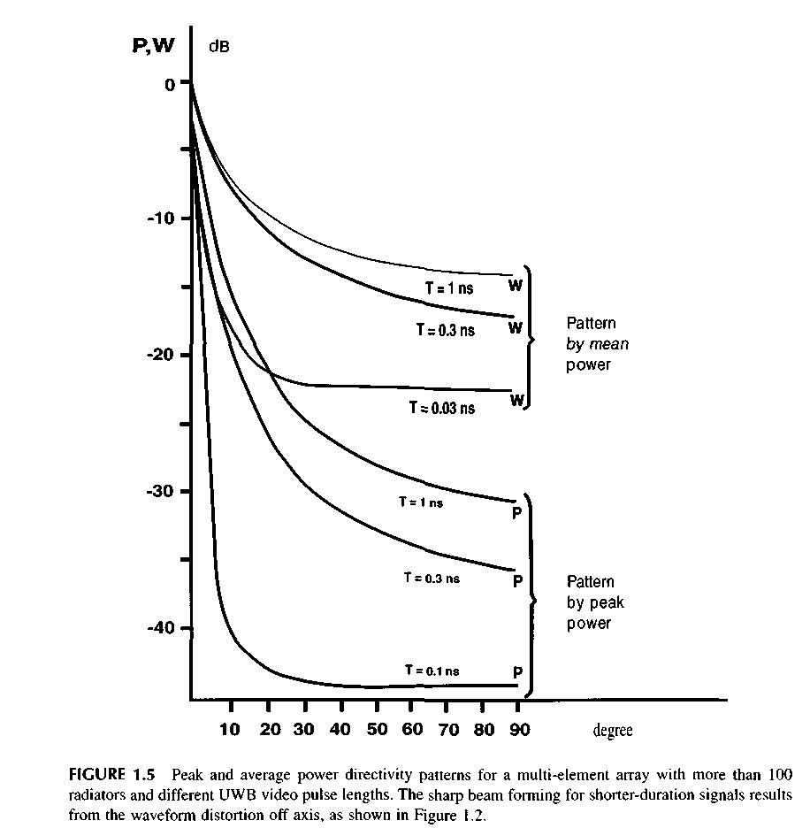
Figure 1.5 shows the DP of an array made of a great number of radiators (N > 100) and radiating different pulse durations. The diagrams are normalized on the maximum level. Notice that the beamwidth depends on duration of pulse, and the side radiation of an array presents a uniform background and does not have the characteristic large side lobes of narrowband antennas.
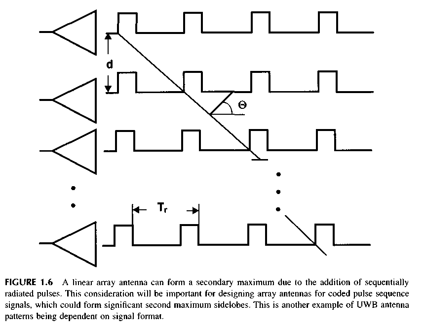
Earlier, we considered the case of an antenna radiating a single pulse. If the antenna array radiates a sequence of pulses under an angle 0O, as shown on Figure 1.6, there is a second maximum DP, similar to an interference beam DP by the narrowband antenna array. It occurs due to addition of pulses radiated in the next periods of recurrence. However, for a narrowband array, the interference beam arises at shift of the next radiators waveform for the period of the high frequency. In a UWB array, the similar second maximum arises at the shift of pulses from the next radiators for the period of recurrence, which considerably exceeds the period of high frequency. It allows us to choose the pulse repetition frequency and UWB array spacing that is rather large, and by that to reduce total of its channels.
The DP presented on the figures corresponds to the rectangular waveform of the field video pulse in the space, and so the DP shape for peak and average powers will be different for the other waveform of the field video pulse. Thus, the antenna DP for the UWB signal depends not only on angular coordinates but also on the time-dependent waveform, which is designated S. Therefore, the expressions for the UWB signal DP will take the form P(Q, ф, S, t) and W(Q, ф, S, t). The signal waveform S relates to its spectrum F by the Fourier transform. Therefore, the expressions for DP can be written in the form: P(0, ф, F, со) and W(0, ф, F со). However, the basic features of the UWB signal DP indicated above for the rectangular video pulse of a field are retained for other waveforms or signal spectra.
Since the DP of an antenna radiating or receiving the UWB signal becomes dependent on the signal waveform and duration, then it is obvious that the directivity factor G(0, ф, S, t), then the gain factor K(Q, ф, S, t) of an antenna and its effective cross section A(0, ф, S, t) become also dependent on the signal parameters. As a result, the directivity factor for the UWB signal is the ratio of the density of the UWB signal power radiated by an antenna in a specified angular direction in the UWB signal bandwidth to the density of the same power signal from an uniformly isotropic radiator in the same bandwidth.
In the case of such determination, the directivity factor depends not only on the geometry of an antenna but also on matching the signal spectrum to the frequency response of an antenna. As a result, the calculation of the antenna directivity factor for the UWB signal presents great difficulties and, for the moment, it can be performed only for its simplest forms.
The main conclusions are as follows:
The antenna DP for the UWB signal is a space-time (space-frequency) function, the characteristics of which depend both on the geometry of an antenna and the signal parameters.
The width and shape of the DP of the array of radiators for the UWB signal are determined by the waveform and duration of a video pulse radiated, on the one hand, and the size of aperture and the radiator spacing, on the other hand, and also by the shape of the DP array radiator.
Interference effects inherent in narrowband signals are not present when the UWB signal is radiated. This circumstance leads to the lack of lobes in the DP structure. In this case, the increase in the distance between array elements allows for making the DP extremely narrow without the appearance of additional diffraction maxima.
4. The directivity factor and the effective cross section of antennas using UWB signals are functions of time and the shape of the signal.
1.3.3 The Target Scattering Cross Section for UWB Signals
One of the most complicated matters in the UWB location is the problem of signal reflection from targets and the target scattering cross section obtained when using these signals. The formal calculation of the scattering cross section, which does not depend on the signal waveform, is given by
![]()
where R is the distance to a target for which a wave incident on it can be considered as a plane one; Es is the intensity of the electric field, which is determined by the target reflection, at the radar receiving antenna; and E0 is the intensity of the electric field incident on a target. In essence, this formula compares the power density of a reflected wave arriving at the radar with the power density of a target-incident wave.
Scattering theory generally assumes that the individual elements of a target scatter the energy of an incident wave independently of one another, so this target is considered as a total set of elements, each of them being an independent brilliant point. Generally speaking, such a representation of a target is not sufficiently justified, since the target elements can be mutually shadowed, and also multiple reflections of a wave are possible between the elements of a target.
Let us consider the process of signal reflection from an individual brilliant point. The parameters of a reflected pulse will depend on the waveform of the pulse response characteristic of a local element and can be determined as the convolution of this characteristic, h(t), with the function f(t) describing a target-incident signal. The integral transformation of the frequency response of a signal-spectrum target can be used for this purpose.
The pulse response characteristic of a local element, h(t), can be derived in the general form by solving the Maxwell equations for a signal defined as the delta-function 8(7) or its approximation and the space area that does not contain irrelevant current sources. However, the solution of these equations in the general form can be made only for a limited number of simplest elements and cannot find wide application.
The geometrical optics techniques are relatively simple, but they do not provide an answer in a number of cases and, in particular, for plane surfaces. The physical optics techniques allow for solving this problem, but they do not provide the answer at the shadow boundary. The physical
and geometrical theories of diffraction enable us to correct results obtained within the approximation of the physical and geometrical optics, but they do not allow for estimating the contribution of a surface traveling wave to the signal scattering over an arbitrary-shape body. The matter is that a significant contribution to the pulse response characteristic of various targets is made by the so-called creeping waves, which are the surface waves propagating in the shadow region and enveloping a scatterer. A whole number of new techniques has been recently developed for their account, the singular expansion technique being the most efficient of them. However, it should be stated that the theoretical and computational means are not currently available to offer a reasonably accurate estimate of the scattering cross section of a complex target irradiated by the UWB signal.
Let us consider the difference between reflected signals when a target is irradiated by narrowband and UWB signals. The spatial physical length of a narrowband signal is equal to cxNB > L, where L is the size of a target and ciUWB < L for an UWB signal. The "long" narrowband signal reflected from all N brilliant points will present a sum of N arbitrary-phase harmonic oscillations or their vector sum. In this case, the target scattering cross section is equal to
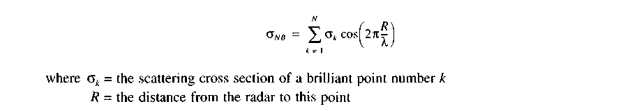
Since a sum of one-frequency harmonic oscillations is also a harmonic oscillation, then the reflected signal will present an invariable amplitude and arbitrary-phase sinusoidal wave.
The summation of harmonic signals reflected from the different points of a target may lead, in respect to some angular directions, to the compete compensation of the field reflected in the radar direction, which is equivalent to the null formation in the secondary target DP.
We have a different picture when the UWB signal, which has cxUWB « L, is reflected from a target. In this case, the reflected signal will represent the sequence of N video pulses randomly arranged in the interval and T= L/c, forming the so-called image of a target, as shown in Figure 1.3.
Video pulses making the whole image may have different amplitude. It depends on the scattering cross section of the corresponding brilliant point of the target. The polarity of these pulses may change. This depends on the magnetic permeability of the material that reflects the signal. When reflecting from a conductor, the electric component of the field changes its polarity. However, when reflecting from materials with high magnetic permeability, the wave polarity does not change. Finally, video pulses reflected from the target may change their initial (e.g., rectangular) form. This will happen if the brilliant points of the target have resonance properties as well as the frequency range that is less than the spectrum of the UWB signal. Besides, the form of the reflected signal will be complicated by re-reflections of video pulses from the brilliant points.
![]()
If we assume that each brilliant point of a target reflects equal energy, then oUWB > Оыв actually in all cases, since
As a result, the target scattering cross-section becomes time-dependent so that oUWB = oUWB(t). If the UWB signal processing algorithm allows for adding the reflections from individual brilliant point (see Chapter 2 of this book), then the target scattering cross section is not time dependent.
Thus, the UWB signal provides a gain in the scattering cross section magnitude. This circumstance, as well as the absence of nulls in the secondary DP of a target, favors a more stable target observation.
Two factors determine the UWB signal conversion when it is scattered by a target. The first one is related to the geometry and orientation of a target and leads to the conversion of one radiation video pulse into a video pulse burst. The second factor is related to the difference of the waveform (or spectrum) of a signal irradiating the target element from the pulse response (or frequency) characteristic of this element. This circumstance results in the change of the waveform of a single video pulse of the burst.
For the UWB signal, the target scattering cross section is a time function. In the case of the matched processing of the reflected UWB signal, the target scattering cross section will be larger than that for a narrowband signal. The secondary DP of a target will not have nulls arising under the action of a narrowband signal owing to the interference of waves reflected from different target elements. This circumstance provides for a more reliable and stable reception of reflected signals.
1.3.4 The UWB Radar Range Equation
The important aspect of the theory of radar observation when using UWB signals is the change in the meaning of parameters in the range equation. In the case under consideration, the directivity factor of a transmitting antenna, G, the effective cross section of a receiving antenna, A, and the effective scattering cross section of a target, oUWB, become dependent on time and signal parameters; i.e., they are nonstationary. Now, this equation involves not only constants but time functions. This feature leads to the other form of the range equation wherein the range is a nonstationary quantity and varies depending on the signal waveform and time.
![]()
where E = the energy of a radiated signal
p = the losses in all the systems of a radar
q - the threshold signal-to-noise ratio
NQ = the spectral density of noise power
It should be noted that a UWB radar features specific energy losses that are not found in narrowband radars. For instance, under the conditions of short-pulse transmission, losses arise owing to the antenna rejection of the lower frequencies of the signal spectrum and the mismatch of this signal to the frequency response of an antenna. Calculation of the magnitude of losses and ways to allay these losses are considered at the end of this chapter.
Under such conditions, these losses may be caused by the absence of information on the space parameters of targets. Losses can reach 10 to 12 dB in the case of the mismatched processing of a signal reflected from a target when the dimensions of this target and the number of its brilliant points are not known. The distinctive features of UWB signals processing are considered in Chapter 2 of this book. The same section contains description of the suggested method to process such signals and avoid the above mentioned losses.
1.3.5 Electromagnetic Compatibility
When UWB radars are used, an important problem is presented by their electromagnetic compatibility with other radio electronic systems and facilities because, in this case, the frequency diversity of other systems is practically impossible.
When UWB radar operates jointly with conventional narrowband radar, only a slight portion of the UWB radar signal energy enters the frequency bandwidth of the narrowband radar receiver. Really, the time constant of the input circuit of a narrowband receiving device, X, = 1/A/, which determines the rise time of the input signal amplitude up to the prescribed value, will be much longer than the pulse length of an UWB radar, x. The bandwidth of a given UWB radar and that of the narrowband radar may differ by three orders of magnitude pulse lengths, e.g., 1 ns and 1 (is. This means that jamming occurring in the narrowband radar receiver due to this UWB pulse of duration x has no time to reach a noticeable magnitude in the receiver.
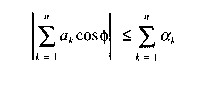
Besides, when both narrowband radar and UWB radar radiate equal powers, this UWB radar has the unit power per unit of the bandwidth (W/MHz), which is approximately lower by three orders of magnitude. This means that only about one-thousandth of the UWB signal power arrives at the narrowband radar receiver. As a result, the total attenuation of the UWB signal in the narrowband radar receiver is about 60 dB, as compared with the influence of the signal of similar narrowband radar on this receiver. An additional effect may be provided if narrowband radars use asynchronous jamming protection equipment and the range selection of received signals. Figure 1.7 shows the dependence of the attenuation factor of the UWB radar interference, k, on the carrier frequency,/, of narrowband radar where, in the figure, A/is the narrowband system bandwidth and F is the UWB radar signal bandwidth.
When a narrowband radars interferes with a UWB radar, one efficient jamming protection is the frequency rejection by cutting narrowband radar signals out the UWB radar signal spectrum. This is usually done during signal processing, as shown in several of the experimental radar sets in Chapter 12.
When two or more UWB radars operate jointly, it is advisable to use the time division of the signals of stations. Because of the short UWB radar signal length and the relative pulse duration reaching value of 106 to 107, the interference of neighboring radar occupies a very small range
section. When radars are mutually synchronized, this section can be blanked without adverse effects to target detection. Interference gating is possible in the radar computer after the estimation of the coordinates of an interfering station has been performed. Considering that interference owing to its short length occupies an insignificant portion of the range, its presence featuring corresponding coloration may be allowed in the output data of a station. The computation show that the area of the mutual influence of UWB radars does not exceed 70 to 80 km at 1 MW peak radiated power. On the other extreme, interference from narrowband systems is a major problem in UWB radar design.
1.4 MOVING TARGET SELECTION IN THE UWB RADAR AND PASSIVE JAMMING PROTECTION
The detection of airborne targets by ultra-wideband (UWB) radar involves interference problems from both natural and man-made sources. The selection of a moving target detection system must be designed around the particular UWB radar system technical features. On the one hand, considerable reduction of the pulse volume substantially decreases the target scattering cross section of the interference, facilitating the observation of the target on its background. On the other extreme, the small pulse volume enhances the influence of those interference elements that can change their position by entering or leaving the pulse volume for the pulse-repetition period. These sources increase the uncompensated residues at the output of the interleaved periodic compensation (IPC) system, thus reducing its effectiveness. The present section is devoted to the investigation of these peculiar features and their influence on the interference immunity of the UWB radar provided with the IPC.
A small pulse volume permits moving targets to be separated without using the Doppler effect. If, over the repetition period Tr, a target travels a distance exceeding a range element (30 cm at x = 1 ns), then, when interleaved periodic subtraction is applied, the signal of this target will be separated, and the signals of stationary or low-mobility targets will be suppressed. Such and IPC system must the following condition to operate:
![]()
where vR = the radial velocity of a target
This system of selection lacks "blind" velocities and does not impose special requirements on the coherence of radiated signals. The target velocity is always unambiguously measured. The target radial velocity v^ can be determined in the selection system by the variation of the range to a target. The minimum determined velocity of a target would be equal to
![]()
One of the main characteristics of the passive interference that determines the effectiveness of the moving target selection (MTS) system is the correlation function of the interfering reflections. Let us consider its peculiar features with respect to the UWB signal.
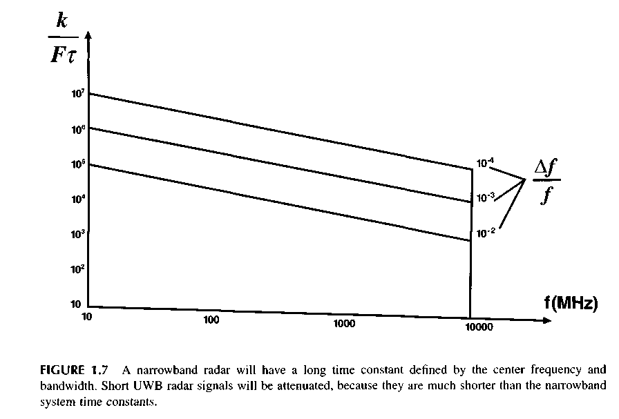
Figure 1.8 gives the normalized correlation functions of the passive jamming Rn at different values of T. As shown in the figure, for the narrowband signals, the correlation function depends very little on the pulse duration. However, at x < Tav (where Tm, = the period of oscillation at the average spectrum frequency, and o(/ = the root-mean-square deviation of the Doppler frequency of the interference), then the decorrelation of the passive interference is observed as the pulse duration
is decreased. Physically, it can be explained by the fact that the decrease of the duration of pulse т brings about the increase of the maximum and, consequently, medium frequency of the spectrum. As a result, the spectrum of the moving passive interference is extended, which reduces the effectiveness of the MTS. On the other hand, with the reduction of the pulse duration, the pulse volume is decreased and, respectively, the power of the passive interference is diminished. Therefore, the interference immunity of the UWB radar should be considered taking account of two opposite factors for a decrease in the pulse duration.
The reduction of the pulse volume (i.e., decrease in the power of the passive interference)
An increase in the interperiodic decorrelation of the passive interference (i.e., the decrease in the coefficient of suppression of the MTS)
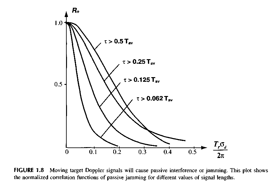
Figure 1.9 shows the dependence the signal-to-interference ratio Q at the output of the systems of the single and twice interleaved periodic compensation (IPC-1 and IPC-2) on duration of UWB signal x, at different values of period repetition Tr. The value Q is normalized rather so that Q0 is the signal-to-interference ratio at x, = Tav and at relative width of a spectrum of passive interference ouTrl2% = 0.1. As it follows from the figure, there are two extremes. The first of them (maximum) falls on the values of duration of the pulse x, = 0.5Ги1,. At x, > 0.5ТШ prevailing is the first factor, and at x, < 0.5 Tm, is the second. With the further decrease in x„ the MTS stops influencing the interference immunity because of complete decorrelation of the interference, and only the first factor remains—reduction of the pulse volume. The level of interference is once again decreased, and Q increases. Thus, the position of the second extreme (minimum) corresponds to the complete decorrelation of the interference and absence of the velocity selection. For the most effective rejecter (IPC-2), these regularities are displayed more distinctly due to the stronger sensitivity to the correlation properties of the interference.
Let us note that, with the decrease in the relative width of the passive interferences spectrum, GdTr /2л, the position of the second extreme is shifted to the left toward the lower-duration x. It means that, with the decrease in the width of the Doppler spectrum of the interference and increase in the pulse repetition frequency, the complete decorrelation of the interference will occur with the shorter signal duration. Within the limits for the non-fluctuating passive interference the decrease in the pulse duration does not influence the MTS effectiveness. Thus, using MTS with respect to the UWB signal is advisable with rather narrowband interferences (local objects) in the radar with the relatively high repetition frequency (i.e., with the small range).
1.5 SHORT VIDEO PULSE FEATURES IN UWB RADAR
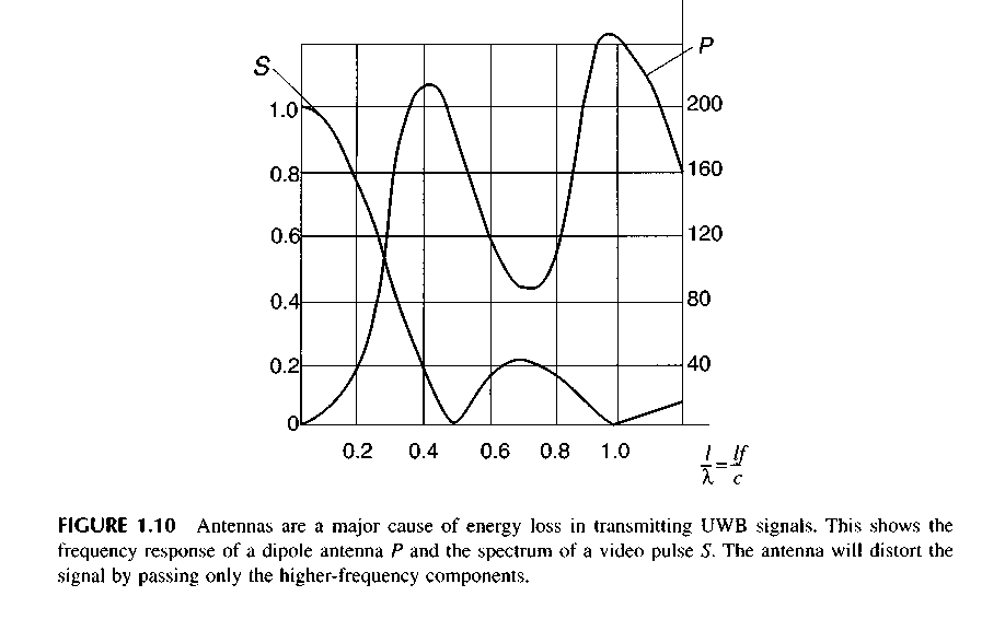
One of the peculiar features of the UWB radar operating with short video pulses with duration т is additional losses of energy. The point is that any antenna does not radiate in the range of frequencies lower than some fmin. On the other hand, the frequency spectrum of any video pulse
has the maximum at the zero frequency. The basic energy of the pulse is concentrated in the band of frequencies A/ and restricted by some fmax usually lying in the region of the first zero of its spectrum. As a result, the frequency characteristic of the antenna and spectrum of the signal appear to be unmatched. Part of the energy that did not fall into the antenna frequency band will be lost. This is seen well in Figure 1.10, which gives the frequency characteristic of the Hertzian dipole P (length /) and spectrum of the rectangular pulse S. With respect to the signal, the antenna is essentially a high-frequency filter.
The notion of the spectral efficiency r\^f was introduced to account for these losses and is a part of the total efficiency of the transmitting device. This efficiency determines the relative share of the energy of the sounding pulse falling into the operating frequency band of the antenna.
![]()
where Ws = full pulse energy
Wf — the energy of that part of the pulse spectrum falling into the antenna frequency band
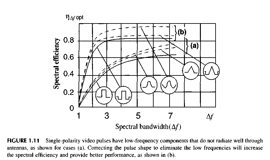
For the single-polarity pulses, the spectral losses can be rather significant. It is possible to reduce these losses by selecting an optimal duration, x „ for each pulse form in the given band of frequencies that will have the maximum value x\ufopl spectral efficiency. The curve "a" in Figure 1.11 shows the dependence of T\&forn on Д/ for three simple single-polarity pulses: rectangular, bell-shaped, and triangular. For all considered pulses at A/'< 3, the maximum efficiency f\Afmax < 50%, which essentially worsens the efficiency of a radar.
The spectral efficiency r\Af can be improved by changing the radiating pulse spectrum. With this aim in mind, spectrum S2(f) of the correcting pulse u2(t) is subtracted from spectrum S,(/) of the basic single-polarity pulse ux(t). The form and intensity of this spectrum were selected so that,
in the summation spectrum S^f) = St(f) - S2(t), the low-frequency components for f < fmi„ were considerably smaller than in the basic spectrum 5,(/}, and, for/>/„„„, the changes were insignificant. The corrected bioolar sounding Dulse will be
![]()
Now the spectral efficiency will depend on the parameters of basic and correcting pulse.
The possible maximum values of the spectral efficiency Цл/ор, have been determined for the simplest corrected pulses, consisting of the difference between two single-polarity pulses, each of which has a simple waveform of rectangular, bell-shaped, or triangular.
The dependencies of r\Afopt on A/ computed for different forms of the basic and correcting pulses, are shown in curve (b) of Figure 1.11. The introduction of a corrected pulse appreciably improved the radar efficiency.
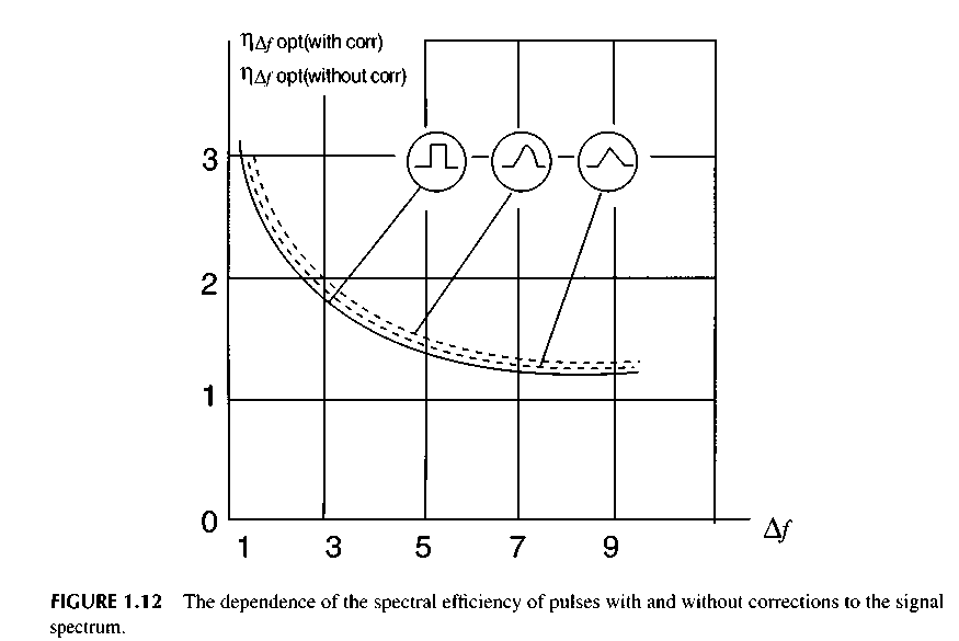
Figure 1.12 gives the curves indicating the dependence of the ratio of the maximum spectral efficiency of the pulses with the correction and without correction r\Afopl<with тгг/ЛлРр,{,.ш,и, corn on the signal spectrum Af. These curves make it possible to estimate the effectiveness of correction of the pulse form so as to increase the spectral efficiency. With the growth of A/, the correction of the pulse form becomes less effective, decreasing from 2 at A/= 3 down to 1.2 at A/= 10.
![]()
and we shall get for the summary spectrum
In the general case, the correcting pulse u2(t) can be shifted relative to the basic pulse by the time t0. Then it can be written that
![]()
Figure 1.13 shows the dependence of the maximum spectral efficiency Цупр, on the relative delay у - t(/x and the correcting pulses of different forms on the basic rectangular pulse. Curves (a)
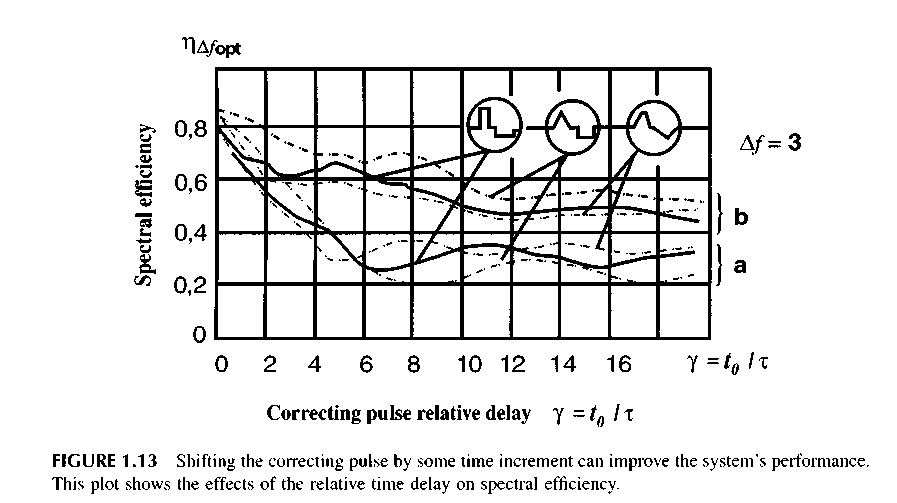
From a practical point of view, the greatest interest will be the corrected pulses, whose basic and correcting pulses do not overlap by time, i.e., when t0 > ft,/2 + x2/2J. For the case у > 1.5, the
pulses follow each other, and r\Afup, becomes less than at у = 0 but remains higher than in the uncorrected pulse case.
Thus, when selecting video pulse UWB radar waveforms, it is necessary to take into account the spectral efficiency because, for the singe-polarity pulses, it can be considerably less than 1. This is especially true of the pulses having the ratio of the high spectrum frequency to the lower one equal to A/ < 3. In this case, the efficiency does not exceed 50 percent.
By increasing A/, the spectral efficiency increases so that, at Af~ 10, it can reach 85 to 90%. Therefore, it is advisable to use the correction of sounding pulses at A/< 3, which provides higher values of spectral efficiency. The correction of the pulse waveform makes it possible to increase the spectral efficiency at Af< 3 by two times, and about 1.2 times at Af~ 10.
REFERENCES
Harmuth, H., Nonsinusoidal Waves for Radar and Radio Communications. Academic Press, New York, 1981. Translation into Russian. Radio i Svyaz, Moscow, 1985.
Harmuth, H., "Radar Equation for Nonsinusoidal Waves." IEEE Transactions on Electromagnetic Compatibility, No. 2, v. 31, 1989, pp. 138-147.
L. Astanin and A. Kostylev, Fundamentals of Ultra-Wideband Radar Measurements, Radio i Svyaz, Moscow, 1989. (Published as Ultrawideband radar measurements: analysis and processing, IEE, UK, London, 1997.)
Stryukov В., Lukyannikov A., Marinetz A., Feodorov N., "Short impulse radar systems." Zarubezh-naya radioelectronika No. 8, 1989, pp. 42-59.
Immoreev, I., "Use of Ultra-Wideband Location in Air Defence." Questions of Special Radio Electronics. Radiolocation Engineering Series. Issue 22, 1991, pp. 76-83.
Immoreev, I. and Zivlin, V., "Moving Target Indication in Radars with the Ultra-Wideband Sounding Signal." Questions of Radio Electronics, Radiolocation Engineering Series, Issue 3, 1992.
Shubert, K. and Ruck, G., "Canonical Representation of Radar Range Equation in the Time Domam."SPIE Proceedings: UWB Radar Conference, Vol. 1631, 1992.
Immoreev, I. and Vovshin, В., "Radar observation using the Ultra Wide Band Signals (UWBS)," International Conference on Radar, Paris, 3-6 May, 1994.
Immoreev, I. and Vovshin, В., "Features of Ultrawideband Radar Projecting." IEEE International Radar Conference, Washington, May, 1995.
Immoreev, I., Grinev, A., Vovshin В., and Voronin, E., "Processing of the Signals in UWB Videopulse Underground Radars," International Conference, Progress in Electromagnetions Research Symposium. Washington, DC, 22-28 July, 1995.
James D. Taylor (ed.), Introduction to Ultra-Wideband Radar Systems. CRC Press, Boca Raton, FL, 1995.
Osipov M., "UWB radar," Radiotechnica, No. 3, 1995, pp. 3-6.
Bunkin B. and Kashin V. "The distinctive features, problems and perspectives of subnanosecond video pulses of radar systems." Radiotechnica, No. 4-5, 1995, pp. 128-133.
Immoreev, I., "Ultrawideband (UWB) Radar Observation: Signal Generation, Radiation and Processing." European Conference on Synthetic Aperture Radar, Konigswinter, Germany, 26-28 March, 1996.
Immoreev, I., "Ultrawideband Location: Main Features and Differences from Common Radiolocation," Electromagnetic Waves and Electronic Systems. Vol. 2, No. 1, 1997, pp. 81-88.
Immoreev I. and Teliatnikov L. "Efficiency of sounding pulse energy application in ultrawideband radar." Radiotechnica, No. 9, 1997, pp. 37-48.
Immoreev, I. and Fedotov, D. "Optimum processing of radar signals with unknown parameters," Radiotechnica, No. 10, 1998, pp. 84-88.
Immoreev, I., "Ultra-wideband radars: New opportunities, unusual problems, system features," Bulletin of the Moscow State Technical University, No. 4, 1998, pp. 25-56.
Основные
особенности сверхширокополосных (СШП)
радаров и их отличия от обычных
узкополосных радаров
Иммореев И.Я.
СОДЕРЖАНИЕ
Введение…………………………………………………………………………………
Информационные возможности СШП радаров……………………………………….
Основные отличия СШП радаров от традиционных узкополосных РЛС……………
Селекция движущихся целей в СШП радаре…………………………………………
Особенности использования энергии коротких видео импульсов в СШП радаре...
Литература…………………………………………………………………………………
1.1. Введение
Большинство традиционных радиотехнических систем имеет узкую полосу частот, а в качестве несущего колебания для передачи информации использует гармонические (синусоидальные) сигналы. Причина проста: синусоида является собственным колебанием LC контура - наиболее элементарной и потому распространенной электрической колебательной системы. А резонансные свойства этой системы позволяют легко выполнять частотную селекцию необходимых сигналов. Поэтому частотная селекция является в радиотехнике основным способом разделения информационных каналов, а большинство радиотехнических систем имеет полосу частот, намного меньшую их несущей частоты. Вся теория и практика современной радиотехники опирается на эту особенность.
В тоже время узкая полоса частот ограничивает информативность радиотехнических систем, поскольку количество информации, передаваемой в единицу времени, прямо пропорционально этой полосе. Для повышения информационных возможностей системы необходимо расширять ее полосу частот. Альтернативой является только увеличение времени передачи информации.
Особенно актуальна эта проблема для радиолокации, где время наблюдения за целью всегда очень ограничено. Обычные радары с полосой частот, не превышающей 10% от несущей частоты, практически исчерпали свои информационные возможности. Поэтому одним из путей дальнейшего развития радаров является переход к сигналам с широкой и сверхширокой полосой частот.
Для создания СШП радаров, как и любой другой техники, необходимы некоторые основы теории, позволяющие грамотно рассчитывать их характеристики. Теория также необходима для определения требований к элементам радаров и разработки аппаратуры: устройств формирования, излучения, приема и обработки СШП сигналов. Однако, несмотря на то, что в последние годы появляется все больше литературы по СШП радарам, удовлетворительная и систематизированная теория до сих пор отсутствует. Причина достаточно объективна. Процесс СШП радиолокационного наблюдения значительно отличается от аналогичного процесса при использовании традиционных узкополосных сигналов. Изучение этих отличий позволяет понять, когда традиционная теория радиолокационного обнаружения может быть использована при проектировании СШП радаров, когда этой теорией пользоваться нельзя и необходимо применение новых методов.
В настоящей главе рассматриваются новые информационные возможности, которые дает радарам применение СШП сигналов; основные отличия СШП радаров, связанные с применением таких сигналов, от традиционных узкополосных радиолокационных систем, а также некоторые технические решения, позволяющие реализовать СШП радары.
1.2. Информационные возможности сверхширокополосных радаров
В СШП локации повышение информативности происходит благодаря уменьшению импульсного объема локатора по дальности. Так, при изменении длительности зондирующего импульса с 1 мкс до 1 нс глубина импульсного объема уменьшается с 300 м до 30 см. Можно сказать, что инструмент, который исследует пространство, становится значительно более тонким и чувствительным.
Уменьшение длительности сигнала в СШП локаторе позволяет:
повысить точность измерения расстояния до цели и разрешающую способность по дальности; в результате повышается разрешающая способность локатора по всем координатам, поскольку разрешение целей по одной координате не требует их разрешения по другим координатам;
произвести распознавание класса и типа цели, поскольку принятый сигнал несет информацию не только о цели в целом, но и об ее отдельных элементах;
повысить эффективность и упростить аппаратуру защиты от всех видов пассивных помех – дождя, тумана, аэрозолей, металлизированных полос, поскольку эффективная поверхность рассеяния (ЭПР) помех в малом импульсном объеме становится соизмеримой с ЭПР цели;
устранить интерференционные провалы в диаграмме направленности (ДН) антенны при наблюдении за целью, которая находится под низким углом места, поскольку сигнал, отраженный от цели и сигнал, переотраженный от земли, разделяются во времени, что позволяет произвести их селекцию;
устранить лепестковую структуру вторичных ДН облучаемых целей, так как колебания, отраженные от отдельных частей цели не интерферируют; тем самым повышается вероятность правильного обнаружения цели;
изменить характеристики излучения (ширину и форму диаграммы направленности), изменяя параметры излучаемого сигнала; в том числе получить сверхузкую ДН;
повысить устойчивость локатора к воздействию внешних узкополосных электромагнитных излучений и помех.