

6 Report contents
6.1 Answers on control questions.
6.2 The list of all nodes in network and list of active nodes only.
6.3 The list of emergency signals in nodes. Explain each of them.
6.4 Actions on recovering the system after indicated faults.
6.5 Conclusions.
Laboratory work №14
Management of MPS power supply system
1 Objectives
To study general characteristics of MPS. To gain skills in controlling and maintenance of MPS.
2 Key positions
2.1 General points. MPS power supply system is intended to provide continuity of service for comm systems by 48V voltage and output current in a range of 12A to 24A (depending on quantity of internal rectifiers). The basic components provide protection for accumulator groups from overloads and damages. The MPS is designed for many different comm systems, and for SI2000 as well.
You can control and manage the MPS from the following devices:
- local PC via the RS232 interface;
- from the display using buttons (optional);
The power supply system can transmit emergency signals to the following:
- telephone exchange (RS232 or RS485 interfaces) and through the MN;
- distributing frame through the isolated emergency terminations.
There are two common variants of MPS installation. The first means that the MPS is installed into separated frame of WRA type. The second means that it has to be installed into ETS frame. However, it can be installed into any case using special mount.
MPS is modular, thus having primary and secondary components. Secondary components provide extra control abilities.
The primary system components are:
1) the rear blade, providing:
- connection of 1 to 3 rectifiers;
- connection of AC via terminations;
- distribution of DC to the loads via two tubular fuses V2 & V3;
- connecting the accumulator units;
- Measuring the rectifier and load currents using two shunt resistors (25A max)
- Disconnection of accumulator in case of its low voltage via the battery termination;
- management and maintenance of the entire system using the microcontroller.
2) automatic switch CB1 for battery protection;
3) automatic switch CB2 for load protection;
4) battery temperature sensor SB;
5) accumulator batteries;
5) terminations for connection to the AC network;
6) protection of system from overvoltage;
The secondary components:
- display that outputs measured values and emergency signals;
- two buttons for system control;
- temperature sensor SA of environment temperature;
The configuration scheme of MPS is depicted on fig. 14.1
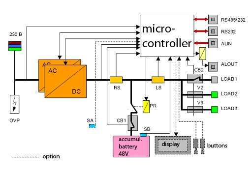
Figure 14.1 – Configuration scheme of MPS
AC/DC - rectifier;
LS – shunt resistor for load current measurement;
CB1 – automatic switch for battery protection;
CB2 - automatic switch for load protection;
V2, V3 – fuses for load protection;
PR – battery termination;
RS – shunt resistor for rectifier current measurement;
SA – temperature sensor for environment temperature measurement;
SB – temperature sensor for battery environment measurement;
OVP – overvoltage protection.
Controlling the MPS using buttons, that are situated on the front panel, allow to perform the following tasks in addition to mentioned above:
- output of system voltage;
- output of temperature voltage coefficient in batteries;
- blocking/unblocking the voltage termocompinsation;
- blocking/unblocking the battery charging current limitation;
- blocking/unblocking the function of switching the batteries off in case of high environment temperature;
- blocking/unblocking the fast battery charging function;
- blocking/unblocking the audible emergency signal;
- blocking/unblocking the emergency signals from the environment;
- blocking/unblocking the emergency signal indicating an unauthorized entrance into equipment room, and also for actions caused by user;
- automatic logging the configuration of transformers, fuses and automatic switches;
- selecting the information output device;
The flowchart of parameters set using the MPS buttons is depicted on fig. 14.2
You have to enter the password in order to make changes. This procedure has to be done in a following way:
Push both T1 & T2 buttons and hold them for a few seconds. After time passes, the “SETUP” caption is printed on display for another 5 seconds. After it, the “PASSWORD” caption appears in the top of the display, and in the bottom – eight short lines, like “_ _ _ _ _ _ _ _”. This eight lines are the place to insert the password, which contains eight binary symbols. The default password is “10101010”. While entering the password, T1 button means “1”, and T2 - “0” and proceeding the next symbol. If the password is incorrect, the “SETUP” caption appears on display. In this case you should reenter the password or wait for about 30 seconds to let the system return to the main window. If the password is correct, the “SET U” submenu appears on display, and your login is registered into the logfile with record LOGIN FROM DISPLAY. You can change the password from the terminal, connected to the system via RS232 interface (with RJ/6 connector on the front side of ARC).
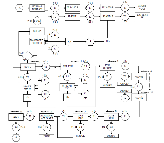
If someone else has already logged in into terminal or MN, the “BUSY!” caption will appear on the display after pushing buttons. Thus, you are not able to configure the system until another administrator log out.
Another submenus may be selected in a cycle from the first submenu using the T1 button. If the system voltage value or the temperature voltage coefficient are changed in the first/second menu, then system passes automatically to the next submenu after 10 seconds (e.g. from SET U into SET TVC, from SET TVC into TVC ON or OFF). After the item name stays 5 seconds on the display, it starts moving to the left with a speed of 1 symbol per half of a second, followed by a comment; after comment passes, the cycle is repeated. It is repeated until one of buttons is pushed (T1 is intended to pass to the next menu item, and T2 – to set value into chosen item). Otherwise, the system returns to the main window after 30 seconds. After viewing all menu items the system returns you to the first submenu.
The main menu "SETUP" contains the following items:
- SET U OUTPUT VOLTAGE – adjust system voltage;
- SET TVC U/T COMPENSATION COEFFICIENT – adjust temperature voltage coefficient of battery unit;
- TVC ACTIVATE U/T COMPENSATION – blocking/unblocking the voltage termocompensation;
- BCCL BATTERY CHARGE CURRENT LIMIT – blocking/unblocking the battery charging current limitation;
- DISCBAT BATTERY AND LOAD DISCONNECTION AT HIGH TEMPERATURE – blocking/unblocking the function of switching the batteries off in case of high environment temperature;
- BOOST ACTIVATE BOOST CHARGING – blocking/unblocking the fast battery charging function;
- AUDIO ACTIVATE AUDIO ALARM – blocking/unblocking the audible signals;
- ALM01 BOOST CHARGING – blocking/unblocking the emergency signals (“fast battery charging”);
- ALM09 FIRE – blocking/unblocking the fire emergency signal;
- ALM10 TRANSMISSION EQUIPMENT FAILURE – blocking/unblocking the transmission systems malfunction emergency signal;
- ALM11 CRITICALLY HIGH TEMP. OF ENVIRONMENT – blocking/unblocking the emergency signal about critically high environment temperature;
- ALM12 CRITICALLY LOW TEMP. OF ENVIRONMENT – the same, but for critically low temperature;
- ALM13 OPEN DOOR 1 – blocking/unblocking the broken open door “1” alarm signal;
- ALM14 UNLOCKED DOOR 1 – blocking/unblocking the lock break “1” alarm signal;
- ALM15 OPEN DOOR 2 – the same, but marked as “2”;
- ALM16 UNLOCKED DOOR 2 – the same, but marked as “2”;
- ALM21 SYMMETRY FAILURE OF BATTERY BLOCKS – blocking/unblocking the critical battery asymmetry emergency signal;
- ALM 22 INCONSISTENT EQUIPMENT – blocking/unblocking the inconsistent equipment alarm signal;
- ALM 35,36,37,38 User defined comment – blocking/unblocking the emergency signal;
- FUSE CFG FUSES AUTOMATIC CONFIGURATION – automatic log recording for automatic switches and fuses configuration;
- UNIT CFG UNITS AUTOMATIC CONFIGURATION – automatic log recording for transformers' configuration;
- ALMPANEL ACTIVATE ALARM PANEL – activation of emergency signalization panel. After activation, TERMINAL ACTIVATE TERMINAL (activation of control terminal) is instead of ALMPANEL item;
- EXIT – exit from "SETUP" menu;
Returning to the main window from the SETUP menu is carried out by selecting EXIT menu and pushing T2 button for less than a second or by waiting for another 30 seconds.
3 Control questions
3.1 For what the MPS is intended?
3.2 What does the MPS provide?
3.3 Using what and due to what the MPS OA&M is carried out?
3.4 What MPS configuration variants do you know?
3.5 What are the primary MPS components?
4 Home task
4.1 Answer the control questions in writing.
4.2 Learn the MPS characteristics.
4.3 Get acquainted with MPS OA&M.
5 Lab task
5.1 Take a look on configuration system of MPS.
5.2 Familiarize with hardware realization of MPS and write about it in short.
5.3 Familiarize and outline all possible variants of MN connection to the MPS.
5.4 Familiarize with OA&M for MPS and outline your reflections in short.
6 Report contents
6.1 Answers on control questions.
6.2 Describe your results on performing the control procedures with MPS.
6.3 Conclusions.
References
1. Документация: Si 2000. Цифровая коммутационная система. Введение в управление.
2. Документация: Si 2000. Цифровая коммутационная система. Описание системы.
3. Документация: Si 2000. Цифровая коммутационная система. Дополнительные услуги.
4. Документация: Si 2000. Справочник по эксплуатации и техническому обслуживанию MPS.
5. www.iskratel.com/ru
6. www.monis.ua