2.2Bpm Process Engine
2.2.1Introduction
Business process management (BPM) is a holistic management approach focused on aligning all aspects of an organization with the wants and needs of clients. It promotes business effectiveness and efficiency while striving for innovation, flexibility, and integration with technology. BPM attempts to improve processes continuously. It can therefore be described as a "process optimization process." It is argued that BPM enables organizations to be more efficient, more effective and more capable of change than a functionally focused, traditional hierarchical management approach.
Activiti is a light-weight workflow and Business Process Management (BPM) Platform targeted at business people, developers and system admins. Its core is a super-fast and rock-solid BPMN 2 process engine for Java. It's open-source and distributed under the Apache license. Activiti runs in any Java application, on a server, on a cluster or in the cloud. It integrates perfectly with Spring, it is extremely lightweight and based on simple concepts.
2.2.2What is bpmn?
The BPM market has longtime been fragmented because there was no consensus amongst BPM vendors. Several standards and specifications tried to fill that gap in the past, but none gathered enough traction in the industry to become an accepted standard for doing BPM. But luckily, times are changing, and over the past years BPM vendors have sat together to create a standard that unifies the BPM landscape. That standard is called 'BPMN', which stands for 'Business Process Model and Notation', and is developed and maintained by the Object Management Group (OMG) since 2004.
The first version of the BPMN specification (versions 1.x, first version released in 2004) focussed on graphical notation only, and became quickly popular within the business analyst audience. This means that the BPMN 1.x specification defines how concepts such as a human task, an executable script, automated decisions, etc. are visualized in a vendor-neutral standardized way. The second version (2.0), extends that focus to include execution semantics and a common exchange format. This means that BPMN 2.0 process definition models are not only exchangeable between graphical editors, but those models can also be executed as-is on any BPMN 2.0 compliant engine such as Activiti.
2.2.3Bpmn 2.0 constructs Custom extensions
The BPMN 2.0 standard is a good thing for all parties involved. End-users don't suffer from a vendor lock-in that comes by depending on a proprietary solution. Frameworks, and particularly open-source frameworks such as Activiti, can implement a solution that has the same features as those of a big vendor. Due to the BPMN 2.0 standard, the transition from such a big vendor solution towards Activiti is an easy and smooth path.
The downside of a standard however, is the fact that it is always the result of many discussions and compromises between different companies (and often visions). As a developer reading the BPMN 2.0 XML of a process definition, sometimes it feels like certain constructs or ways to do things are too cumbersome. Since Activiti puts ease of development as a top-priority and introduces something called the 'Activiti BPMN extensions'. These 'extensions' are new constructs or ways to simplify certain constructs that are not in the BPMN 2.0 specification.
Events
Events are used to model something that happens during the lifetime process. Events are always visualized as a circle. In BPMN 2.0, there exist two main event categories: catching or throwing event.
Catching: when process execution arrives in the event, it will wait for a trigger to happen.
Throwing: when process execution arrives in the event, a trigger is fired.
Timer events definitions
Timer events are events which are triggered by defined timer. They can be used as start event, intermediate event or boundary event
Start events
A start event indicates where a process starts. The type of start event (process starts on arrival of message, on specific time intervals, etc.), defining how the process is started is shown as a small icon in the visual representation of the event.
None start event
A ‘none’ start event technically means that the trigger for starting the process instance is unspecified. This means that the engine cannot anticipate when the process instance must be started.
A ‘none’ start event is visualized as a circle with no inner icon (Figure 2.6).
Figure 2.6 – Graphical notation of none start event

Timer start event
A timer start event is used to create process instance at given time. It can be used both for processes which should start only once and for processes that should start in specific time intervals.
Note: a subprocess cannot have a timer start event.
A none start event is visualized as a circle with clock inner icon (Figure 2.7).
Figure 2.7 – Graphical notation of timer start event

End events
An end event signifies the end (of a path) of a (sub)process. An end event is always throwing. This means that when process execution arrives in the end event, a result is thrown. The type of result is depicted by the inner black icon of the event.
None end event
A 'none' end event means that the result thrown when the event is reached is unspecified. As such, the engine will not do anything extra besides ending the current path of execution.
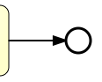
A none end event is visualized as a circle with a thick border with no inner icon (Figure 2.8).
Figure 2.8 – Graphical notation of none end event
Error end event
When process execution arrives in an error end event, the, the current path of execution is ended and an error is thrown. This error can catched by a matching intermediate boundary error event. In case no matching boundary error event is found, the execution semantics default to the none end event semantics.
Important note: a BPMN error is NOT the same as a Java exception. In fact, the two have nothing in common. BPMN error events are a way of modeling business exceptions. Java exceptions are handled in their own specific way.
An error end event is visualized as a typical end event (circle with thick border), with the error icon inside (Figure 2.9). The error icon is completely black, to indicate the throwing semantics.
Figure 2.9 – Graphical notation of error end event

Sequence flow
A sequence flow is the connector between two elements of a process. After an element is visited during process execution, all outgoing sequence flow will be followed. This means that the default nature of BPMN 2.0 is to be parallel: two outgoing sequence flow will create two separate, parallel paths of execution.
A sequence flow is visualized as an arrow going from the source element towards the target element. The arrow always points towards the target (Figure 2.10).
Figure 2.10 – Graphical notation of sequence flow
![]()
Conditional sequence flow
A sequence flow can have a condition defined on it. When a BPMN 2.0 activity is left, the default behavior is to evaluate the conditions on the outgoing sequence flow. When a condition evaluates to true, that outgoing sequence flow is selected. When multiple sequence flow are selected that way, multiple executions will be generated and the process will be continued in a parallel way.
Note: the above holds for BPMN 2.0 activities (and events), but not for gateways. Gateways will handle sequence flow with conditions in specific ways, depending on the gateway type.
A conditional sequence flow is visualized as a regular sequence flow, with a small diamond at the beginning. The condition expression is shown next to the sequence flow (Figure 2.11).
Figure 2.11 – Graphical notation of conditional sequence flow

Default sequence flow
All BPMN 2.0 tasks and gateways can have a default sequence flow. This sequence flow is only selected as the outgoing sequence flow for that activity if and only if none of the other sequence flow could be selected. Conditions on a default sequence flow are always ignored.
A default sequence flow is visualized as a regular sequence flow, with a 'slash' marker at the beginning (Figure 2.12).
Figure 2.12 – Graphical notation of default sequence flow
![]()
Gateways
A gateway is used to control the flow of execution (or as the BPMN 2.0 describes, the tokens of execution). A gateway is capable of consuming or generating tokens.
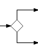
A gateway is graphically visualized as a diamond shape, with an icon inside. The icon shows the type of gateway (Figure 2.13).
Figure 2.13 – Graphical notation of gateways
Exclusive gateway
An exclusive gateway (also called the XOR gateway or more technical the exclusive data-based gateway), is used to model a decision in the process. When the execution arrives at this gateway, all outgoing sequence flow are evaluated in the order in which they are defined. The sequence flow which condition evaluates to true (or which doesn't have a condition set, conceptually having a 'true' defined on the sequence flow) is selected for continuing the process.
An exclusive gateway is visualized as a typical gateway (i.e. a diamond shape) with an 'X' icon inside, referring to the XOR semantics. Note that a gateway without an icon inside defaults to an exclusive gateway (Figure 2.14).
Figure 2.14 – Graphical notation of exclusive gateway

Parallel Gateway
Gateways can also be used to model concurrency in a process. The most straightforward gateway to introduce concurrency in a process model, is the Parallel Gateway, which allows to fork into multiple paths of execution or join multiple incoming paths of execution.
The functionality of the parallel gateway is based on the incoming and outgoing sequence flow:
fork: all outgoing sequence flow are followed in parallel, creating one concurrent execution for each sequence flow.
join: all concurrent executions arriving at the parallel gateway wait in the gateway until an execution has arrived for each of the incoming sequence flow. Then the process continues past the joining gateway.
An important difference with other gateway types is that the parallel gateway does not evaluate conditions. If conditions are defined on the sequence flow connected with the parallel gateway, they are simply neglected.
A parallel gateway is visualized as a gateway (diamond shape) with the 'plus' symbol inside, referring to the 'AND' semantics (Figure 2.15).
Figure 2.15 – Graphical notation of parallel gateway

User task
A 'user task' is used to model work that needs to be done by a human actor. When the process execution arrives at such a user task, a new task is created in the task list of the user(s) or group(s) assigned to that task.
A user task is visualized as a typical task (rounded rectangle), with a small user icon in the left upper corner (Figure 2.16).
Figure 2.16 – Graphical notation of user task

Script Task
A script task is an automatic activity. When a process execution arrives at the script task, the corresponding script is executed.
A script task is visualized as a typical BPMN 2.0 task (rounded rectangle), with a small 'script' icon in the top-left corner of the rectangle (Figure 2.17).
Figure 2.17 – Graphical notation of script task

Java Service Task
A Java service task is used to invoke an external Java class.
A service task is visualized as a rounded rectangle with a small gear icon in the top-left corner (Figure 2.18).
Figure 2.18 – Graphical notation of Java Service Task

Business Rule Task
A Business Rule task is used to synchronously execute one or more ruleset or rules. Activiti uses Drools Expert, the Drools rule engine to execute business rules. For this release, the .drl files containing the business rules have to be deployed together with the process definition that defines a business rule task to execute those rules. This means that all .drl files that are used in a process have to be packaged in the process BAR file like for example the task forms. For more information about creating business rules for Drools Expert please refer to the Drools documentation at JBoss Drools.
A Business Rule task is visualized the with a table icon (Figure 2.19).
Figure 2.19 – Graphical notation of business rule task

Email task
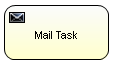
Activiti allows to enhance business processes with automatic mail service tasks that send e-mails to one or more recipients, including support for cc, bcc, html content, etc. An email task is visualized the with an mail icon in the top left corner (Figure 2.20).
Figure 2.20 – Graphical notation of email task
Manual Task
A Manual Task defines a task that is external to the BPM engine. It is used to model work that is done by somebody, which the engine does not need to know of, nor is there a system or UI interface. For the engine, a manual task is handled as a pass-through activity, automatically continuing the process from the moment process execution arrives into it.
A manual task is visualized as a rounded rectangle, with a little 'hand' icon in the upper left corner (Figure 2.21).
Figure 2.21 – Graphical notation of manual task

Java receive task
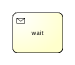
A receive task is a simple task that waits for the arrival of a certain message. Currently, we have only implemented Java semantics for this task. When process execution arrives at a receive task, the process state is committed to the persistence store. This means that the process will stay in this wait state, until a specific message is received by the engine, which triggers the continuation of the process past the receive task.
A receive task is visualized as a task (rounded rectangle) with a message icon in the top left corner (Figure 2.22). The message is white (a black message icon would have send semantics).
Figure 2.22 – Graphical notation of java receive task
Task listener
A task listener is used to execute custom Java logic or an expression upon the occurrence of a certain task-related event.
Boundary events
Boundary events are catching events that are attached to an activity (a boundary event can never be throwing). This means that while the activity is running, the event is listening for a certain type of trigger. When the event is caught, the activity is interrupted and the sequence flow going out of the event are followed.
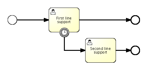
Timer Boundary Event
A timer boundary event acts as a stopwatch and alarm clock. When an execution arrives in the activity where the boundary event is attached to, a timer is started. When the timer fires (e.g. after a specified interval), the activity is interrupted and the sequence flow going out of the timer boundary event are followed.
A timer boundary event is visualized as a typical boundary event (i.e. circle on the border), with the timer icon on the inside (Figure 2.23).
Figure 2.23 – Graphical notation of timer boundary event
Error Boundary event
An intermediate catching error on the boundary of an activity, or boundary error event for short, catches errors that are thrown within the scope of the activity on which it is defined.
Defining a boundary error event makes most sense on an embedded subprocess, or a call activity, as a subprocess creates a scope for all activities inside the subprocess. Errors are thrown by error end events. Such an error will propagate its parent scopes upwards until a scope is found on which a boundary error event is defined that matches the error event definition.
When an error event is caught, the activity on which the boundary event is defined is destroyed, also destroying all current executions within (eg. concurrent activities, nested subprocesses, etc.). Process execution continues following the outgoing sequence flow of the boundary event.
A boundary error event is visualized as a typical intermediate event (Circle with smaller circle inside) on the boundary, with the error icon inside (Figure 2.24). The error icon is white, to indicate the catch semantics.
Figure 2.24 – Graphical notation of error boundary event
SubProcess
A subprocess is an activity that contains other activities, gateways, events, etc. which on itself form a process that is part of the bigger process. A subprocess is completely defined inside a parent process (that's why it's often called an embedded subprocess).
Subprocesses have two major use cases:
Subprocesses allow hierarchical modeling. Many modeling tools allow that subprocesses can be collapsed, hiding all the details of the subprocess and displaying a high-level end-to-end overview of the business process.
A subprocess creates a new scope for events. Events that are thrown during execution of the subprocess, can be caught by a boundary event on the boundary of the subprocess, thus creating a scope for that event limited to the subprocess.
Using a subprocess does impose some constraints:
A subprocess can only have one none start event, no other start event types are allowed. A subprocess must at least have one end event. Note that the BPMN 2.0 specification allows to omit the start and end events in a subprocess, but the current Activiti implementation does not support this.
Sequence flow can not cross subprocess boundaries.
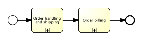
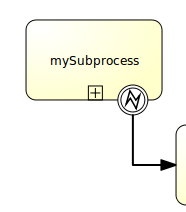
A subprocess is visualized as a typical activity, i.e. a rounded rectangle. In case the subprocess is collapsed, only the name and a plus-sign are displayed, giving a high-level overview of the process (Figure 2.25).
Figure 2.25 – Graphical notation of subprocess