

Вопросы для самоконтроля
Перечислите основные особенности языка описания изобретения.
Перечислите все разделы описания изобретения и расскажите о их предназначении.
В чем состоят особенности библиографического описания к патентам Великобритании и США и укажите способы их передачи на русский язык.
Составьте собственные примеры с клише, используемыми в реферате патента и приведите вариант их перевода на русский язык.
В чем заключаются лексические и грамматические особенности перевода на русский язык разделов «Предпосылки к созданию изобретения», «Обзор существующего уровня техники», «Критика прототипа».
На что необходимо обращать внимание при переводе на русский язык раздела Резюме (сущность) изобретения?
Используя словарь, дополните список терминов, используемых при описании чертежей, приведенный в главе 4.2.4
В чем заключаются лексические и грамматические особенности перевода на русский язык раздела «Подробное описание изобретения»? Найдите примеры для каждого случая в тексте на перевод № 14.
Перечислите системы составления формулы изобретения и укажите их отличительные черты.
Глава 5
ПРАКТИКА ПЕРЕВОДА ПАТЕНТОВ США И ВЕЛИКОБРИТАНИИ
Text for translation №1
What is a Patent?
A Patent protects an invention and gives its proprietor the exclusive right to manufacture, use, import or sell in the UK a product embodying the invention covered by the Patent. It can therefore be used to stop others from copying your invention, or deter them from doing so, without your consent.
What criteria must my invention meet to be patentable?
To be patentable your invention must meet two main criteria. Firstly, it must be novel which means that it must have never been publicly disclosed anywhere in the world before the date that you filed your Patent Application. Secondly, it must have an inventive step which means that it must be something more than just an obvious modification of something that has already been disclosed to the public.
How do I know if my invention meets the requirements of novelty and inventive step?
Before a Patent can be granted, the UK Patent Office conducts a search through previously published Patents and Patent Applications in an attempt to find any documents to show that your invention does not meet the requirements of novelty and inventive step. The Examiner then examines your Patent Application in light of the disclosure in each of the documents found in the search and issues an Official Letter setting out his opinion on patentability.
In some cases, it is worthwhile conducting an unofficial search before filing an Application to find out whether your idea is novel. However, searching is a difficult and time consuming task and usually expensive. Therefore, it is generally more cost effective to file a Patent Application and wait for the results of the official Patent Office Search.
What form does a Patent Application take?
A Patent Application must include a detailed written specification that contains a full description and drawings describing and illustrating all the aspects of your invention. It is very important to ensure that all the features of your invention that you may wish to protect are described, as it is not possible to add further information once the Application has been filed. The Patent specification must enable a reader of it to fully understand your invention and be able to put it into practice. A Patent Specification must also include a set of claims defining the monopoly for which you are seeking exclusivity.
What are “Claims”?
The claims are the most important part of any patent specification and are a series of numbered paragraphs that define the scope or extent of protection of the invention. Claim 1 is the most important claim and must recite only the essential features of your invention and in the broadest possible terms thereby providing protection for the broad underlying principle or concept of your invention, rather than any specific embodiment of it. Claim 1 must not contain any features that are inessential to the invention otherwise a person may copy your invention, without infringing your patent, by omitting that inessential feature from their product.
What happens if the Patent Office finds that my invention as defined in my Patent claims are not novel or lack inventive step?
In this case, assuming the Examiner is correct, we can usually amend your patent application by adding to claim 1 a preferable feature of your invention referred to in the specification which has not been disclosed in any of the documents found by the Examiner. Although the scope of protection will be reduced, the grant of a patent is still the likely outcome in the majority of cases.
What is the difference between Patents Copyright, Registered Designs, Unregistered Design Right and Registered Trademarks?
Copyright arises on creation of a work and protects the actual form of the work rather than the idea or concept itself. It can be used to prevent unauthorised copying of aesthetic creations such as literary, dramatic, musical and artistic works and computer programs.
• Unregistered Design Right is similar to Copyright and can be used to prevent unauthorised copying of a product.
• Copyright and Unregistered Design Right arise automatically on creation of the work and no official registration is needed. • Registered Designs protect only the shape and appearance of an article having a distinctive appearance and are monopoly rights which must be registered at the UK Designs Registry.
• Registered Trademarks protect the name and any associated sign or logo that distinguishes the goods or services provided by one company from those of other companies.
A disadvantage with Copyright and Unregistered Design Right is that to enforce them successfully you must be able to prove that you have been copied. This is not necessary with monopoly rights such as Patents, Registered Designs and Registered Trademarks.
When should I file a Patent Application?
In view of the requirement for novelty, a patent application must be filed before ANY public disclosure of an invention is made ANYWHERE IN THE WORLD.
When can I disclose my patent application?
Once the application has been filed, you are free to disclose it. Shortly after filing, the UK Patent Office will issue a filing receipt together with a unique application number identifying your application, It is advisable to mark your product with an indication that a Patent Application has been filed together with this number so that competitors know that a Patent has been filed. This will act as a deterrent against unauthorized copying.
Does the public and my competitors have access to my Patent Application?
Once filed, your Patent Application will remain secret for 18 months. After this, assuming that you have not withdrawn or abandoned your application, it will be published and a copy of the specification will be available to anyone who wishes to see it.
How long does it take to get a Patent ?
Usually, it takes 2-3 years before a Patent is granted. However, a patent can sometimes be granted sooner. You are of course free to disclose and exploit your invention whilst the application is pending.
How long does a Patent last?
A UK Patent lasts for an initial period of 4 years from the filing date. Renewal fees must then be paid annually to keep the Patent in force for a maximum of 20 years.
Can I obtain corresponding Patent protection abroad?
A UK Patent affords its proprietor protection in the UK only. Corresponding protection can be obtained in other countries but applications in those countries must be filed within twelve months of the filing date of your UK application, particularly if you have disclosed your invention during that twelve month period. Any foreign applications filed during this time will effectively have the same filing date as your UK Patent Application.
Filing Patent Applications in foreign countries is expensive so it is important to establish that your idea is commercially viable in the 12 months following the filing of your UK Patent Application to ensure that the cost of filing the foreign applications is justified
FROM http://www.vennershipley.co.uk
Text for translation №2
Why patents are important
If you have an idea for a new product which you think could be commercially successful, there are several different forms of protection which the product can enjoy. There is copyright, which will automatically come into existence whenever an original artistic work (including an engineering drawing) is created. There is an unregistered design right which again is automatically created and protects the look of the product itself. There is a common law trademark right which will build up over time when a distinctive word or logo is used to identify the product in the course of trade. You don't have to pay for any of these, although you can apply for registration of some designs and trademarks which will give you a monopoly right effective from the date on which you apply for registration. This can often be beneficial and, generally speaking, these registered rights do not cost an arm and a leg.
So, if you want to protect the look of a product or the trademark you use to sell it, it's not particularly difficult or expensive. You can very often do it yourself using a few brochures from the UK Patent Office and their user-friendly enquiry line. But neither of these forms of protection can stop someone else from taking the principles on which your product works and making a similar product which looks different and is sold under a different trademark. So how do you do that?
The only way to get protection for an invention is to apply for a patent. An invention usually relates to a new principle or arrangement which allows the new product to work in a particular way. Our fundamental patents relate to the basic principle of putting two cyclones of increasing efficiency into a vacuum cleaner to increase the overall separation efficiency of the cleaner. It doesn't matter what the machine looks like or what trademark is used to sell it, any cleaner which incorporates the features of our patent claims will fall within the scope of the patent. Inventions can relate to methods (like methods of manufacture or industrial processes) as well as to products or parts of products.
Let's step back a bit. The patent system was introduced over 100 years ago (although some form of this type of protection has been around for about 350 years) as an incentive to get inventors to disclose their ideas to the general public and so promote technical advancement in general. In return for the public disclosure, the inventor got a monopoly right for a fixed term and, after that, anyone and everyone would be free to make use of the idea and – hopefully – improve upon it. Life has moved on a bit since then and, although the framework is still the same, the reasons why people apply for patents are a bit different these days. Essentially, a patent gives the proprietor the right to stop someone else making a product having the features of the granted claims and therefore patents are generally regarded as legal weaponry rather than publications of information.
As you will appreciate, a patent is (or can be) a very valuable piece of property. It is therefore not particularly surprising that it is also a lot harder, more expensive and more time-consuming to obtain. You will either need to put in a lot of hard work and research yourself, or you will need to pay a professional patent agent to do some of the work for you. Using a patent agent does increase the cost of getting a patent quite dramatically, but you can then be sure of getting good advice and a well-drafted patent at the end of the day. If you are going to use your patent as a legal weapon, surely you'd like it to be as sharp as possible?
Before you apply for a patent
There are some fundamental rules that apply to patents in almost all countries and if you break them, even in ignorance of the consequences, you may still get yourself into an irretrievable situation. So, first and foremost:
RULE NUMBER ONE: DON'T TELL ANYONE ABOUT YOUR IDEA BEFORE YOU FILE THE PATENT APPLICATION.
This may sound impractical. You do, after all, need to assess whether or not the idea is commercially sound, whether or not it can be manufactured and, if so, whether it can be sold for an acceptable price. But, somehow, you will have to find out these things without actually telling the person you're speaking to what it is you want to make (more specifically, to protect). If you do feel the need to bare all to someone you trust completely, make sure that they know before you tell them your idea that you are telling them this in confidence and that they must not disclose it to anyone else without your express permission. Ideally, the confidentiality of the disclosure you make should be written down in a confidentiality agreement and signed by the person to whom you are making the disclosure. This is particularly important if you are talking to a commercial contact or potential business colleague. The other way is to get your patent application on file before you start talking to anyone about your idea. You can talk to a Chartered Patent Agent in complete confidence because all Chartered Patent Agents work under strict rules of confidentiality. It would be a bit ludicrous if you couldn't discuss the idea for which you need protection with the person who is going to help you get that protection!
The reason for all this confidentiality is that, to be patentable, an invention must be novel. An invention is not novel if it has been made available to the public (anyone will do) before the date of filing the patent application. If you show your idea to a potential manufacturer without a confidentiality agreement in place, the novelty of the idea is destroyed and you are no longer entitled to a patent for it. This allows the manufacturer to rush off and make the product himself without any acknowledgement of your contribution, financial or otherwise.
The next thing you need for your idea to be patentable is an inventive step. This means that the invention must not be obvious to someone who is "skilled in the art" to which the invention relates. How you assess whether something is inventive over what is already known just cannot be explained in a note like this, but it is something in which patent agents develop experience and on which they can give advice. Do not expect the UK Patent Office to give advice of this type – it does not provide this sort of function.
To decide whether your idea is inventive, you have to find out what has been done before in the relevant field. You can instruct professional searchers to look through earlier patents and patent applications but this will inevitably be expensive (possibly more than £5,000) and will probably only result in you being sent a small mountain of documents in several different languages which you will then have to try to decipher. There are other ways. Look on the Internet. Go to the British Library or a good regional library with a patent information section and make maximum use of the Helpdesk. Hopefully, you have some knowledge of the field in which you're interested – use what knowledge you've got and do some digging around (without disclosing to others what you're actually looking for).
Assuming that you believe that your idea is novel and inventive, you have to decide whether you are going to apply for your patent yourself or employ a patent agent. If you don't have an endless supply of free evenings and can afford the charges, go to a patent agent, at least for an initial consultation. Many private practice firms will give individuals an initial consultation (about half an hour) free of charge. Ask for this – if your chosen firm won't do it, go somewhere else. And make sure when you go for a consultation that the patent agent you will be seeing has the correct technical background – you don't want a chemist trying to deal with something which is basically electronic. The Chartered Institute of Patent Agents also offers "clinics" where individuals can get free advice – ring them for details. If you go to a solicitor for advice, make sure that he has experience in patent matters – many don't, especially outside the big cities.
You won't get a draft application out of a first consultation. You should get a professional opinion as to whether your idea is generally patentable (although the patent agent will not be able to guarantee anything because he will not have full details of everything which has been done before) and whether there is any point in you continuing with a patent application. Make sure you are told what it will cost to continue and that the agent outlines the whole procedure so that you have a general understanding of what lies in store. You may decide, when you hear what the costs might be, that the whole thing is a waste of time and money and you might just as well go home. But remember that, if you do not apply for a patent at the outset, you cannot turn back the clock and file later on, unless you have not in the meantime disclosed your invention. Filing a patent application can also help to convince a potential partner or manufacturer that you are serious about your idea and have been prepared to put your own time and money behind it.
Getting a patent
The basic procedure for getting a patent in most countries is as follows:
The application is filed containing a full description of the invention and a set of claims defining the scope of protection requested by the applicant;
A search is carried out by the Patent Office to see if they can find any earlier published documents which affect the novelty or inventive step of the invention as claimed;
The application is published (normally about 18 months after the application is filed);
The applicant requests examination of the claims;
The Patent Office carries out a detailed examination of the claims and the application as a whole, raising objections if appropriate and giving the applicant an opportunity to amend the application to overcome the objections, if this can be done;
The patent will be granted if all objections have been overcome.
This is just an overview of a typical procedure: some countries have very different procedures and some roll various parts of this type of procedure together. There will be formal requirements to be met at different stages of the procedure as well, such as filing powers of attorney, making sure that the drawings meet specific requirements, and so on. The time taken to complete the procedure varies from country to country but typically takes between 3 and 5 years.
FROM http://www.dyson.ie/invent
Text for translation № 3. The Abstract
Abstract of WO200704166
Cellular phone games based on television archives allow users to play games on their cellular phones wherein the games are based on archived television programs. The game is able to be played simultaneously between competitors or on demand. Game data and video data are combined into one file and are sent to participating cellular phones so that the required information is received at the same time at each cellular phone. Each cellular phone contains software to manipulate the game and video data so that the user is able to play the game. The game is played by watching video clips from archived television programs and then selecting choices related to the video clips using the inputs on the user's cellular phone. User scores are determined based on the answers to the questions related to the video clips and results are distributed to the participants.
FROM: www.wipo.org/pctdb/en
Text for translation № 4. The Abstract
Abstract of WO2007040770
A system and method for decoding a received television signal is disclosed. The system includes an input to receive a digital audio signal and a digital variable deemphasis module to modify the amplitude of the digital audio signal based on a plurality of variable coefficients. The system also includes an exponential digital root mean square (ERMS) detector to provide level detection of the digital audio signal. The plurality of variable coefficients of the digital variable deemphasis module are digitally computed based on an output of the digital ERMS detector.
FROM: www.wipo.org/pctdb/en
Text for translation № 5. The Abstract
Abstract of KR100326839B
PURPOSE: Provided are a paprika hamburger bun and a method for manufacturing the same by mixing paprika with wheat flour. The manufactured bun has a characteristic taste and flavor, contains beneficial components to the human body, and has various kinds of colors to boost appetite. CONSTITUTION: A paprika hamburger bun is characteristically manufactured by mixing 60-65 wt.% of wheat flour, 5-15 wt.% of milk, 5-10 wt.% of sugar, 0.5-2.0 wt.%of refined salt, 1.0-2.0 wt.% of yeast, 5-10 wt.5of shortening, and 10-14 wt.% of a paprika extract.
FROM: www.wipo.org/pctdb/en
Text for translation № 6. The Abstract
Abstract of WO2007039268
The present invention utilizes wild-type and PKBa-knockout mouse embryonic fibroblasts (MEFs) as well as nucleic acid microarray technology to identify genes whose expression is up-regulated in presence of PKBa during adipogenesis. Using this combined approach, we have identified genes previously unknown to be important for adipogenesis, and describe the use of these genes in drug discovery and as biomarkers.
FROM: www.wipo.org/pctdb/en
Text for translation № 7. The Abstract
Abstract of WO2007040844
A reel for winding a paper roll including: a frame supporting a reel drum and a pair of rails; a reel spool supported for translation by the rails and upon which a paper roll is wound; an endless flexible belt wrapping a portion of the periphery of the reel drum and a portion of the periphery of the paper roll; and a loading member for loading the paper roll against the reel drum and the endless flexible belt.
FROM: www.wipo.org/pctdb/en
Text for translation № 8. Official Gazette publication
US 7,254,840 B2 |
|
|
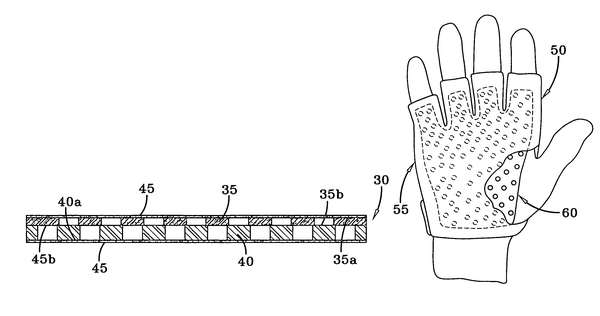
Impact and/or vibration absorbent material and protective glove making use thereof |
|
|
Gary Hammons, Richwood, Ohio (US); Roger W. Kramer, Springfield, Ohio (US); Charles Marks, Springfield, Ohio (US); Kevin Porter, Marysville, Ohio (US); Robert Bogard, Columbus, Ohio (US); Traci Skahill, Hilliard, Ohio (US); and Mark Smith, Marion, Ohio (US) |
||
Assigned to Honda Motor Co., Ltd., Tokyo (Japan) |
||
Filed on Mar. 21, 2005, as Appl. No. 11/84,906. |
||
Prior Publication US 2006/0206980 A1, Sep. 21, 2006 |
||
Int. Cl. A41D 19/00 (2006.01) |
||
U.S. Cl. 2—16 [2/161.6] |
29 Claims |
|
1. An impact and/or vibration absorbent material comprising: a first impact and/or vibration absorbent material layer constructed from a flexible polymeric material, said first material layer including a plurality of holes therein; a second impact and/or vibration absorbent material layer constructed from a polymeric material having a hardness greater than the hardness of said first material layer, said second material layer including a plurality of holes therein; wherein said holes in said first material layer are located to be offset from said holes in said second material layer when said layers are properly assembled to one another; and wherein portions of said first material layer deflect into said holes in said second material layer when said impact and/or vibration absorbent material is subjected to an impact force. |
From The Official Gazette of the United States Patent and Trademark Office. Patents Vol. 1321 Number 2August 14
Text for translation № 9. Official Gazette publication
US 7,254,841 B1 |
|
|
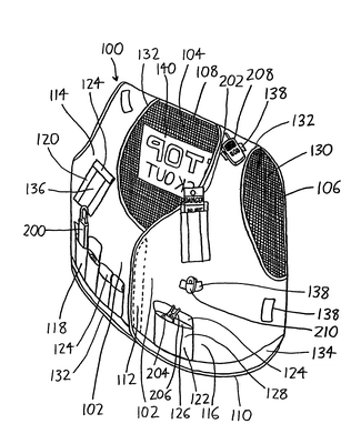
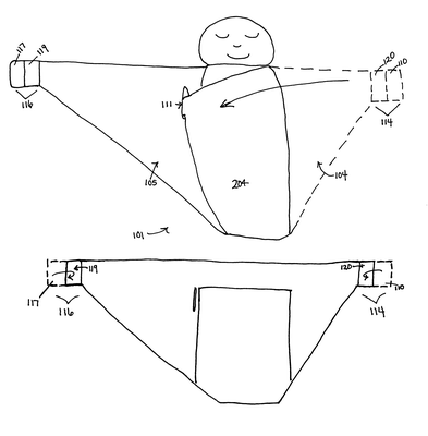
Vest serving as portable lockout station for machine maintenance |
|
|
Steven Curtis Nelson, N5802 Hwy. HH, Mauston, Wis. 53948 (US); and Todd Timothy Johnson, Reedsburg, Wis. (US) |
||
Assigned to Steven Curtis Nelson, Mauston, Wis. (US) |
||
Filed on Jul. 13, 2004, as Appl. No. 10/890,534. |
||
Int. Cl. A41D 1/04 (2006.01) |
||
U.S. Cl. 2—102 [2/94; 2/51] |
21 Claims |
|
1. A portable lockout station garment for imposing a safety lockout on machinery, the garment comprising a vest having: a. a pair of opposing arm openings with a neck opening therebetween, b. a pair of opposing chest flaps descending from the neck opening to a vest waist, the flaps being releasably closable, wherein each of the chest flaps includes: (1) a breast region adjacent the neck opening wherein the breast region situates over a wearer's breast, and (2) an abdomen region adjacent the vest waist wherein the abdomen region situates over a wearer's abdomen, c. two or more lock pockets on the abdomen regions, each lock pocket having a depth greater than its width to accommodate a safety lockout padlock, with two or more safety lockout padlocks, each being situated in one of the lock pockets; d. a key pocket on one of the abdomen regions, the key pocket being sized to accommodate one or more keys, with one or more keys in the key pocket, each key being configured to allow unlocking of one or more of the safety lockout padlocks; e. a tag pocket on one of the breast regions, each tag pocket having a depth greater than its width to accommodate a safety lockout tag, with one or more safety lockout tags in the tag pocket, wherein at least a major portion of the vest is colored in the yellow-orange range. From The Official Gazette of the United States Patent and Trademark Office. Patents Vol. 1321 Number 2August 14
|
Text for translation № 10. Official Gazette publication
US 7,254,847 B2 |
Начало формы Конец формы |
|
Ribbon flow waterfall for spas |
|
|
Richard Kunkel, Murrieta, Calif. (US) |
||
Assigned to Watkins Manufacturing Corporation, Vista, Calif. (US) |
||
Filed on Apr. 01, 2004, as Appl. No. 10/816,505. |
||
Prior Publication US 2005/0223490 A1, Oct. 13, 2005 |
||
Int. Cl. E04H 4/00 (2006.01) |
||
U.S. Cl. 4—507 [4/678] |
11 Claims |

|
||
1. In combination with a spa having a container (20) for holding water with a top rim (15) the improvement being a waterfall structure comprising: a plenum chamber (23) having walls (24, 26), a water inlet (39) and a water outlet (30), the outlet being formed from the walls (24, 26) of the plenum chamber; a spout (13) formed from the walls (24, 26) of the plenum chamber as a continuation of the water outlet (30), the spout (13) passing through the top rim and having a narrow and elongated mouth (14) and a top (17) and bottom (16); a mounting plate (25) bordering the top and the bottom of the spout where the spout passes through the top rim; and a light source (43) attached through the mounting plate at the bottom (16) of the spout (13) to inject light directly into water falling out of the spout (13). From The Official Gazette of the United States Patent and Trademark Office. Patents Vol. 1321 Number 2August 14
TText for translation № 11. Official Gazette publication |
||
US 7,254,849 B1 |
Начало формы Конец формы |
|
Snug & tug swaddling blanket |
|
|
Georgia Gabrielle Fiebrich, Alexandria, Va. (US); and Catherine Nora Hall, Washington, D.C. (US) |
||
Assigned to Go Mama Go Designs, LLC, Alexandria, Va. (US) |
||
Filed on Apr. 17, 2006, as Appl. No. 11/404,922. |
||
Int. Cl. A41B 13/06 (2006.01) |
||
U.S. Cl. 5—482 [5/923; 5/922; 2/69.5] |
16 Claims |
|
|
||
1. An article for swaddling an infant, said article comprising: a sheet of flexible material having an inner surface for receiving the infant and an outer surface, said sheet of flexible material having in combination: a first portion wherein a pouch is secured to an inner surface, said pouch being sized to contain the infant up to at least the infant's upper torso; a reinforced slit disposed adjacent to a first side of the pouch to allow passage through the inner surface to the outer surface; a second portion having cooperating fasteners and adapted to wrap around the infant contained in the pouch and arranged to transit through the reinforced slit and secure to the outer surface of the sheet of flexible material; and a third potion adapted to wrap over and around the infant and is secure to the outer surface of the sheet of flexible material, the second and third portions being tapered to end portions having a horizontal width of about 4 inches, each end portion having a hook fastener component and a loop fastener component disposed thereon, with the hook fastener components being positioned adjacent the loop fastener components. From The Official Gazette of the United States Patent and Trademark Office. Patents Vol. 1321 Number 2August 14
Text for translation № 12. Official Gazette publication |
|||
US 7,254,857 B2 |
|
|
|
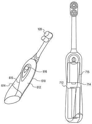
Power toothbrush with unique handle |
|
||
Eduardo Jimenez, Manalapan, N.J. (US); and John Gatzemeyer, Hillsborough, N.J. (US) |
|
||
Assigned to Colgate-Palmolive Company, New York, N.Y. (US) |
|
||
Filed on Jun. 17, 2005, as Appl. No. 11/155,858. |
|
||
Application 11/155858 is a continuation of application No. PCT/US03/39540, filed on Dec. 12, 2003. |
|
||
Claims priority of provisional application 60/434106, filed on Dec. 17, 2002. |
|
||
Prior Publication US 2005/0283929 A1, Dec. 29, 2005 |
|
||
Int. Cl. A61C 17/22 (2006.01); A46B 13/02 (2006.01) |
|
||
U.S. Cl. 15—22.1 [15/28] |
4 Claims |
|
1. A powered toothbrush comprising: a handle portion being formed with a neck at a first end thereof and an interior compartment formed therein at a second end thereof for receiving no more than a single pair of batteries, the second end being disposed substantially opposite to the first end; a head coupled to the neck, the head further including: a base; and one or more carriers coupled to the base, at least one of the carriers being operatively connected to a drive member for moving the one or more coupled carriers in respective directions, wherein the interior compartment is arranged such that each battery of the single pair of batteries received in the interior compartment is generally aligned along a longitudinal axis with said neck and a face of said carrier, said pair of batteries being generally positioned along said longitudinal axis at a predetermined angle from said face of said carrier; wherein said angle is approximately 45°. From The Official Gazette of the United States Patent and Trademark Office. Patents Vol. 1321 Number 2August 14
|
Text for translation № 13.The UK Patent Application
(12) UK Patent Application (19) GB (11) 2 219 995(13)A
(43) Date of A publication 28.12.1989
![]()
(21) Application No 8914216.0
(22) Date of filing 21.06.1989
(30) Priority Data
(31 ) 209297 (32) 21.06.1988 (33) US
383173 07.06.1989
(71) Applicant
Concord Research Corporation
(Incorporated In the USA - Arizona)
15650 North Black Canyon Highway, Phoenix
Arizona 85023, United Slates of America
(72) Inventor
David Radlus Hudson
(74} Agent and/or Address for Service
Gallafent & Co
8 Staple Inn, London, WC1V 7QH United Kingdom
(51) INT CL.
C21D 10/00
(52) UK CL (Edition J)
C1A AG11 AG19 AG22 AG23 AG25 AG26 AG28
AG29 AG3 AG6 AG9 APC
(56) Documents cited
None
(58) Field of search
UK CL (Edition J) C1A APC
On-line search of Derwent World Patent Index
(54) Non-metallic, monoatomic forms of transition elements
(67) Stable, non-metallic, orbitally rearranged monoatomic transition elements selected from the group consisting of cobalt, nickel, copper, silver, gold, palladium, platinum, ruthenium, rhodium, iridium, and osmium having a doublet In the infrared spectra between 1400 and 1600 cm-1 and having a d orbital hole or holes sharing energy with an electron or electrons are described. These materials have specific application in forming catalysts, high-temperature ceramics, refractory materials corrosion resistant materials and they exhibit properties of high temperature super-conductivity and energy production. The materials are produced either from ores which do not analyze by conventional instruments for any of said transition and noble metals, or by conversion of pure metals or metal salts of said elements into the orbitally rearranged monoatomic species.
NON-METALLIC, MONOATOMIC FORMS
OF TRANSITION ELEMENTS
This invention relates to the monoatomic forms of certain transition and noble metal elements, namely, gold, silver, copper, cobalt, nickel and the six platinum group elements. More particularly, this invention relates to the separation of the aforesaid transition and noble metal elements from naturally occurring materials in their orbitally rearranged monoatomic forms, and to the preparation of the aforesaid transition and noble metal elements in their orbitally rearranged monoatomic forms from their commercial metallic forms. The materials of this invention are stable, substantially pure, non-metallic-like forms of the aforesaid transition and noble metal elements, and have a hereto unknown electron orbital rearrangement in the "d", "s", and vacant "p" orbitals. The electron rearrangement bestows upon the monoatomic elements unique electronic, chemical, magnetic, and physical properties which have commercial application.
This invention also relates to the recovery of the metallic form of each of the aforesaid transition and noble metal elements from the orbitally rearranged monoatomic forms.
For the purposes of this application, the following definitions shall apply: transition elements ("T-metals") means the metallic or cationic form of gold, silver, copper, cobalt and nickel, and the six platinum group elements, i.e., platinum, palladium, rhodium, iridium, ruthenium, and osmium; and "ORME" means the Orbitally Rearranged Monoatomic Elemental forms of each of the T-metals.
BACKGROUND OF INVENTION
Inorganic chemists working with soluble salts of noble metals until relatively recently have assumed that the metals were dissolved as free ions in aqueous solutions. In the 1960's, with the advent of greater analytical capabilities, it was established that many elements and in particular the transition metals are present in aqueous solutions as metal-metal bonded clusters of atoms.
Gold metal that has been dissolved with aqua regia, and subsequently converted to gold chloride by repeated evaporation with HCl to remove nitrates, is commonly referred to as the acid chloride solution of AuCl3 or HAuCl4. It has been recognized that the recovery of gold metal from a solution formed from aqua regia is made more difficult in proportion to the amount of HNO3 used in the initial dissolution procedures. It is not commonly understood, however, why the gold that is dissolved with less HNO3 is easier to reduce to the metal from a chloride solution than gold that is dissolved using a greater amount of HNO3. Gold in both solutions is generally regarded as being present in the form of a free gold cation.
It is now recognized by most chemists who regularly handle chlorides of gold that gold metal ceases to disaggregate when the HNO3 is removed and in fact can reaggregate under certain conditions and precipitate out of HCl solutions as metal. This recognition has led to the discovery that gold metal salts will exist in HCl solutions originating from metals as clusters of Au2Cl6, Au3Cl9,
Au4Cl12, up to Au33Cl99. These cluster salts are actually in solution with the HCl and water, and will require different chemical procedures relative to purification problems or oxidation-reduction reactions, depending on the degree of clustering.
Specifically, reduction of clusters of gold having greater than 11 atoms of metal is easily performed since the atoms themselves are spaced from each other in the salt similar to their spacing in the metal itself before dissolution. Reduction of the chloride salt to the metal, therefore, requires a simple reductive elimination of the chlorides that are attached to the metal cluster. It is now known that recovery of precious metals from aqueous solutions is much more difficult when the cluster size becomes smaller and smaller, or in actuality when the metal is better "dissolved."
From the study of the behavior of gold and other transition metals in solution, it is now believed that all such metals have atomic aggregations and occur as at least diatoms under normal conditions of dissolution . Under either acid or strong base dissolution, the transition metal will not normally dissolve beyond the diatom due to the extremely strong interatomic d and s orbital bonding. A gold atom, for example, has a single atom electron orbital configuration of d10s1. When the gold salts originate from a metal having gold-gold bonding, the salts contain very tightly bound diatoms or larger clusters of gold. Under the normal aqueous acid chemistry used for transition metals, solutions of the metals will always contain two or tore atoms in the cluster form.
When instrumental analysis such as atomic absorption, x-ray fluorescence, or emission spectroscopy is performed on solutions containing transition metals, these analyses are based on electronic transitions. The fact that d orbital electron overlap occurs in the metal-metal bonded salt allows an analysis of many of the same characteristic omissions as the metal itself.
GENERAL DESCRIPTION OF INVENTION
During efforts to effect quantitative analytical separations of transition metals from naturally occurring materials, it was discovered that ORMEs exist naturally and are found in salts with alkali metals and/or alkaline earth metals, all of which are coupled with waters of hydration and normally found with silica and alumina. ORMEs are also often associated with sulfides and other mineral compositions.
ORMEs may also, it was discovered, be prepared from commercially available T-metals. For ease of description the invention will be primarily described by the preparation of a gold ORME ("G-ORME") from commercially available metallic yellow gold.
The atoms of each ORME do not have d electron orbital overlap as do their corresponding T-metal clusters. ORMEs do not, therefore, exhibit the same characteristic emissions of their corresponding T-metal when subjected to analysis by instruments which depend upon electronic transitions. ORMEs must, therefore, be identified in new ways, ways which have heretofore not been used to identify T-metals.
An aqua regia solution of metallic gold is prepared. This solution contains clusters of gold chlorides of random size and degrees of aggregation. HCl is added to the solution and it is repeatedly evaporated with a large excess of NaCl (20:1 moles Na to moles Au) to moist salts. The addition of NaCl allows the eventual formation of NaAuCl4, after all HNO3 is removed from the solution. The sodium, like gold, has only one unpaired S electron and, accordingly, tends to form clusters of at least two atoms. The sodium, however, does not d orbitally overlap the gold atom as it has no d electrons, resulting in a surface reaction between the sodium atoms and the gold atoms. This results in a weakening of the gold-gold cluster stability and causes the eventual formation of a sodium-gold linear bond with a weakened d orbital activity in the individual gold atoms. The sodium-gold compound, formed by repeated evaporation to salts, will provide a chloride of sodium-gold. In these salts the sodium and gold are believed to be charged positive, i.e., have lost electrons: and the chlorine is negative, i.e., has gained electrons. When the salts are dissolved in water and the pH slowly adjusted to neutral, full aquation of the sodium-gold diatom will slowly occur and chloride is removed from the complex. Chemical reduction of the sodium-gold solution results in the formation of a sodium auride. Continued aquation results in disassociation of the gold atom from the sodium and the eventual formation of a protonated auride of gold as a grey precipitate. Subsequent annealing produces the G-ORME. The G-ORME has an electron rearrangement whereby it acquires a d orbital hole or holes which share energy with an electron or electrons. This pairing occurs under the influence of a magnetic field external to the field of the electrons.
G-ORMEs are stable and possess strong interatomic repulsive magnetic forces, relative to their attractive forces. G-ORME stability is demonstrated by unique thermal and chemical properties. The white saltlike material that is formed from G-ORMEs after treatment with halogens, and the white oxide appearing material formed when G-ORMEs are treated with fuming HClO4 or fuming H2SO4 are dissimilar from the T-metal or its salts. The G-ORME will not react with cyanide, will not be dissolved by aqua regia, and will not wet or amalgamate with mercury. It also does not sinter at 800C under reducing conditions, and remains an amorphous powder at 1200C. These characteristics are contrary to what is observed for metallic gold and/or gold cluster salts. G-ORMEs require a more negative potential than -2.45 v to be reduced, a potential that cannot be achieved with ordinarily known aqueous chemistry.
The strong interatomic repulsive forces are demonstrated in that the G-ORMEs remain as a powder at 1200C. This phenomenon results from canceling of the normal attractive forces arising from the net interaction between the shielded, paired electrons and the unshielded, unpaired s and d valence electrons. G-ORMEs have no unpaired valence electrons and, therefore, tend not to aggregate as would clusters of gold which have one or more unpaired valence electrons.
G-ORMEs can be reconverted to metallic gold from which they were formed. This reconversion is accomplished by an oxidation rearrangement which removes all paired valence electrons together with their vacancy pair electrons, with a subsequent refilling of the d and s orbitals with unpaired electrons until the proper configuration is reached for the T-metal.
This oxidation rearrangement is effected by subjecting the G-ORME to a large negative potential in the presence of an electron-donating element, such as carbon, thus forming a metallic element-carbon chemical bond. For that metal-carbon bond to occur the carbon must provide for the horizontal removal of the d orbital vacancy of the ORME. The carbon acts like a chemical fulcrum. When the element-carbon bond is reduced by way of further decreasing the potential, the carbon receives a reducing electron and subsequently vertically inserts that reducing electron below the s orbitals of the element, thus forming metallic gold.
The above general description for the preparation of G-ORME from commercially available metallic gold is applicable equally for the preparation of the remaining ORMEs, except for the specific potential energy required and the use of nascent nitrogen (N) rather than carbon to convert the other ORMEs to their constituent metallic form. The specific energies range between -1.8 V and -2.5 V depending on the particular element. Alternatively this rearrangement can be achieved chemically by reacting NO gas with the T-metal ORMEs other than gold. Nitric oxide is unique in that it possesses the necessary chemical potential as well as the single unpaired electron.
SCOPE OF THE INVENTION
The formation and the existence of ORMEs applies to all transition and noble metals of the Periodic Table and include cobalt, nickel, copper, silver, gold, and the platinum group metals including platinum, palladium, rhodium, iridium, ruthenium and osmium, which can have various d and s orbital arrangements, which are referred to as T-metals.
The T-metals, when subjected to conventional wet chemistry will disaggregate through the various known levels, but not beyond a diatom state. The conventional wet chemistry techniques if continued to be applied beyond the normally expected disaggregation level (diatom) in the presence of water and an alkali metal, e.g., sodium, potassium or lithium, will first form a diatom and then electron orbitally rearrange to the non-metallic, mono-atomic form of the T-metal, ie., an ORME.
An ORME can be reaggregated to the T-metal form using conventional wet chemistry techniques, by subjecting the ORME to a two-stage electrical potential to "oxidize" the element to the metallic form.
The ORMEs of this invention exist in nature in an unpure form in various materials, such as sodic plagioclase or calcidic plagioclase ores. Because of their non-metallic, orbitally rearranged monoatomic form, ORMEs are not detected in these ores as the corresponding "metals" using conventional analysis and, accordingly, until the present invention were not detected, isolated or separated in a pure or substantially pure form. Their presence in the nonmetallic form explains the inconsistent analysis at times obtained when analyzing ores for metals whereby the quantitative analysis of elements accounts for less than 100% of the ore by weight.
THE CLAIMS:
1. In a separated and substantially pure, stable form, a non-metallic, orbitally rearranged monoatomic transition or noble metal element selected from the group consisting of cobalt, nickel, copper, silver, gold, palladium, platinum, ruthenium, rhodium, iridium, and osmium having a d orbital hole sharing energy with an electron or electrons, said shared energy identified as a doublet in an infrared spectrum of from between about 1400 and 1600-1 cm.
2. The orbitally rearranged monoatomic element of claim 1 wherein said element is gold.
3. The orbitally rearranged monoatomic element of claim 1 wherein said element is silver.
4. The orbitally rearranged monoatomic element of claim 1 wherein said element is copper.
5. The orbitally rearranged monoatomic element of claim 1 wherein said element is palladium.
6. The orbitally rearranged monoatomic element of claim 1 wherein said element is platinum.
7. The orbitally rearranged monoatomic element of claim 1 wherein said element is ruthenium.
8. The orbitally rearranged monoatomic element of claim 1 wherein said element is rhodium.
9. The orbitally rearranged monoatomic element of claim 1 wherein said element is iridium.
10. The orbitally rearranged monoatomic element of claim 1 wherein said element is osmium.
11. The orbitally rearranged monoatomic element of claim 1 wherein said element is cobalt.
12. The orbitally rearranged monoatomic element of claim 1 wherein said element is nickel.
13. Process of forming a non-metallic, orbitally rearranged monoatomic form of an element selected from the group consisting of cobalt, nickel, copper, silver, gold, palladium, platinum, ruthenium, rhodium, iridium, and osmium from the corresponding element in metal form comprising treating said metal form by forming a salt thereof, exhaustively solubilizing and evaporating said salt in an aqueous medium until a diatom of said metal form is obtained; and thereafter treating said diatom with an alkali metal in the presence of water to form said orbitally rearranged, stable monoatomic form of said element.
14. Process of forming a metal selected from the group consisting of cobalt, nickel, copper, silver, gold, palladium, platinum, ruthenium, rhodium, iridium, and osmium from a material having the corresponding element present in a non-metallic, orbitally rearranged monoatomic stable form of said element, comprising separating said element in said orbitally rearranged monoatomic form from said material, and then subjecting said separated, non-metallic, orbitally rearranged mono-atomic stable form to a two-step negative potential of at least 1.8 to 2.2 V initially, and then to at least 2.5 V until the said element is formed by electroplating techniques.
15. Process of forming a metal selected from the group consisting of cobalt, nickel, silver, palladium, platinum, ruthenium, rhodium, iridium, and osmium from a material having the corresponding element present in a non-metallic, orbitally rearranged monoatomic stable form of said element, comprising subjecting said element in said orbitally rearranged monoatomic stable form to a treatment with nitric oxide at elevated temperatures.
16. Process of treating the stable non-metallic, orbitally rearranged monoatomic transition or noble metal element of claim 1 by subjecting said element to alternate heating and cooling cycles under an inert gas and supplying an external magnetic field to said element until said element no longer exhibits a doublet in the infrared spectrum and exhibits magnetic flux exclusion at temperatures above 200K.
17. The product formed by the process of claim 16.
18. An orbitally rearranged monoatomic element, selected from cobalt, nickel, silver, palladium, platinum, ruthenium, rhodium, iridium, and osmium having a d orbital hole sharing energy with an electron or electrons: having a doublet in its infrared spectrum between 1400 and 1600 cm-1; having non-metallic characteristic, and being in substantially pure form.
19. An orbitally rearranged monoatomic element in substantially pure form and substantially as herinbefore described.
20. A process of forming a non-metallic, orbitally rearranged monatomic form of an element selected from cobalt, nickel, silver, palladium, platinum, ruthenium, rhodium, iridium, and osmium substantially as herein described in any one of the Examples.
21. A non-metallic, orbitally rearranged monoatomic form of an elements selected from cobalt, nickel, silver, palladium, platinum, ruthenium, rhodium, iridium, and osmium prepared by the process claimed in claim 13 or 20,
22. A process of forming a metal from a non-metallic, orbitally rearranged monoatomic form of an element selected from cobalt, nickel, silver, palladium, platinum, ruthenium, rhodium, iridium, and osmium substantially as hereinbefore described.
23. A metal formed by the process claimed in claim 14, 15 or 22. FROM: www.rexresearch.com/ormes/ormes.htm
Text for translation № 14. The US patent
United States Patent |
5,421,089 |
Dubus , et al. |
June 6, 1995 |
Fork with timer
Abstract
A fork with timer comprising a fork having a head, a plurality of spaced tines extended from the head, and a handle extended from the head remote from the tines; timer circuitry connected to the handle of the fork and adapted for providing a cue after an elapsed period of time for indicating to user that another bite of food using the fork may be taken; a replaceable power source connected to the fork and coupled to the timer circuitry with the power source adapted for energizing the timer circuitry; and a switch connected to the fork and coupled between the power source and the timer circuitry with the switch having one orientation for energizing the timer circuitry and another orientation for de-energizing the timer circuitry.
Inventors: |
Dubus; Nicole M. (Santa Cruz, CA), Springfield; Susan (Santa Cruz, CA) |
Appl. No.: |
08/249,191 |
Filed: |
May 26, 1994 |
Current U.S. Class: |
30/142 ; 30/322 |
Current International Class: |
A47G 21/00 (20060101); A47G 21/02 (20060101); A47J 043/28 () |
Field of Search: |
30/123,142,324,137,147,148,149,150,322 446/81,175 |
References Cited [Referenced By]
U.S. Patent Documents
|
|
|
|
|
|
|
4207673 |
|
June 1980 |
|
DiGirolamo et al. |
|
4914819 |
|
April 1990 |
|
Ash |
|
5075970 |
|
December 1991 |
|
Albert |
|
5189793 |
|
March 1993 |
|
Ratzon et al. |
|
|
|
|
|
|
Primary Examiner: Payer; Hwei Siu
Claims
What is claimed as being new and desired to be protected by LETTERS PATENT of the United States is as follows:
1. A fork with timer for providing a cue to a user after an elapsed period of time for indicating that another bite of food using the fork may be taken comprising, in combination:
a rigid dinner fork having a head, four spaced and aligned tines extended from the head, and a handle extended from the head remote from the tines for allowing a user a firm grip for taking a bite of food
timer circuitry connected to the handle of the dinner fork and adapted for providing a cue after an elapsed period of time for indicating to user that another bite of food using the dinner fork may be taken, the timer circuitry further comprising
a countdown timer adapted for counting down a pre-programmed period of time, transmitting countdown signals in sequence during this period of time, and transmitting an event signal when this period of time has elapsed, the countdown timer including automatic reset circuitry for resetting the pre-programmed period of time upon countdown completion for subsequent countdown during a subsequent period of time;
decoder/driver circuitry coupled to the countdown timer and adapted for receiving the countdown signals and event signals during and upon completion of a period of time, transmitting a "go" signal when an event signal is received, transmitting a "stop" signal when an event signal is not received, and transmitting timer display signals upon receipt of countdown signals;
a green light emitting diode and a red light emitting diode each coupled to the decoder/driver circuitry with the green light emitting diode activated when the "go" signal is received and deactivated otherwise, the red light emitting diode activated when the "stop" signal is received and deactivated otherwise, whereby when a period of time has elapsed, the green light emitting diode is activated and the red light emitting diode is deactivated, and when a period of time has not elapsed, the red light emitting diode is activated and the green light emitting diode is deactivated; and
display circuitry coupled to the decoder/driver circuitry with the display circuitry having a numeric display for transmitting a visual indication of elapsed time based upon receipt of timer display signals;
a replaceable power source connected to the dinner fork and coupled to the timer circuitry with the power source adapted for energizing the timer circuitry; and
a switch connected to the handle of the dinner fork and coupled between the power source and the timer circuitry with the switch having one orientation for energizing the timer circuitry and another orientation for de-energizing the timer circuitry.
2. The fork with timer as set forth in claim 1 further comprising:
a one-shot speaker driver coupled to the countdown timer and adapted to transmit a speaker activation signal upon receipt of an event signal; and
a speaker connected to the handle and coupled to the one-shot speaker driver with the speaker adapted for transmitting an audible tone based upon receipt of a speaker activation signal.
3. A fork with timer for providing a cue to a user after an elapsed period of time for indicating that another bite of food using the fork may be taken comprising:
a dinner fork having a head, a plurality of spaced tines extended from the head, and a handle extended from the head remote from the tines;
timer circuitry connected to the handle of the dinner fork and adapted for providing a cue after an elapsed period of time for indicating to user that another bite of food using the dinner fork may be taken, the timer circuitry further comprising:
a countdown timer adapted for counting down a pre-programmed period of time, transmitting countdown signals in sequence during this period of time, and transmitting an event signal when this period of time has elapsed, the countdown timer including automatic reset circuitry for resetting the pre-programmed period of time upon countdown completion for subsequent countdown during a subsequent period of time;
decoder/driver circuitry coupled to the countdown timer and adapted for receiving the countdown signals and event signals during and upon completion of a period of time, transmitting a "go" signal when an event signal is received, transmitting a "stop" signal when an event signal is not received, and transmitting timer display signals upon receipt of countdown signals;
a green light and a red light each coupled to the decoder/driver circuitry with the green light activated when the "go" signal is received and deactivated otherwise, the red light activated when the "stop" signal is received and deactivated otherwise, whereby when a period of time has elapsed, the green light is activated and the red light is deactivated, and when a period of time has not elapsed, the red light is activated and the green light is deactivated; and
display circuitry coupled to the decoder/driver circuitry with the display circuitry having a display for transmitting a visual indication of elapsed time based upon receipt of timer display signals;
a replaceable power source connected to the dinner fork and coupled to the timer circuitry with the power source adapted for energizing the timer circuitry; and
a switch connected to the dinner fork and coupled between the power source and the timer circuitry with the switch having one orientation for energizing the timer circuitry and another orientation for de-energizing the timer circuitry.
4. The fork with timer as set forth in claim 3 further including interface means coupled to the timer circuitry and adapted to be accessible by a user for allowing the pre-programmed period of time to be set as desired.
Description
BACKGROUND OF THE INVENTION
Field of the Invention
The present invention relates to a fork with timer and more particularly pertains to providing a cue to a user after an elapsed period of time for indicating that another bite of food using the fork may be taken with a fork with timer
Description of the Prior Art The use of forks is known in the prior art.
More specifically, forks heretofore devised and utilized for the purpose of eating are known to consist basically of familiar, expected and obvious structural configurations, notwithstanding the myriad of designs encompassed by the crowded prior art which have been developed for the fulfillment of countless objectives and requirements.
By way of example, U.S. Pat. Des. No. 245,141 to Eldridge et al. discloses a fork or other similar article of flatware. U.S. Pat. Des. No. 275,167 to Laslo discloses a fork. U.S. Pat. Des. No. 337,701 to Wilson discloses a fork. U.S. Pat. No. 3,609,865 to Golden discloses a fork-like food utensil. U.S. Pat. No. 4,896,423 to Kinsey discloses an eating fork.
While these devices fulfill their respective, particular objective and requirements, the aforementioned patents do not describe a fork with timer that provides a cue to a user after an elapsed period of time for indicating that another bite of food using the fork may be taken.
In this respect, the fork with timer according to the present invention substantially departs from the conventional concepts and designs of the prior art, and in doing so provides an apparatus primarily developed for the purpose of providing a cue to a user after an elapsed period of time for indicating that another bite of food using the fork may be taken.
Therefore, it can be appreciated that there exists a continuing need for new and improved fork with timer which can be used for providing a cue to a user after an elapsed period of time for indicating that another bite of food using the fork may be taken. In this regard, the present invention substantially fulfills this need.
SUMMARY OF THE INVENTION
In the view of the foregoing disadvantages inherent in the known types of forks now present in the prior art, the present invention provides an improved fork with timer. As such, the general purpose of the present invention, which will be described subsequently in greater detail, is to provide a new and improved fork with timer and method which has all the advantages of the prior art and none of the disadvantages.
To attain this, the present invention essentially comprises, in combination, a rigid fork having a head, four spaced and aligned tines extended from the head, and a handle extended from the head remote from the tines for allowing a user a firm grip for taking a bite of food. Timer circuitry is connected to the handle of the fork and adapted for providing a cue after an elapsed period of time for indicating to user that another bite of food using the fork may be taken.
The timer circuitry includes a countdown timer adapted for counting down a pre-programmed period of time, transmitting countdown signals in sequence during this period of time, and transmitting an event signal when this period of time has elapsed with the countdown timer including automatic reset circuitry for resetting the pre-programmed period of time upon countdown completion for subsequent countdown during a subsequent period of time. The timer circuitry includes decoder/driver circuitry coupled to the countdown timer and adapted for receiving the countdown signals and event signals during and upon completion of a period of time, transmitting a "go" signal when an event signal is received, transmitting a "stop" signal when an event signal is not received, and transmitting timer display signals upon receipt of countdown signals. The timer circuitry includes a green light emitting diode and a red light emitting diode each coupled to the decoder/driver circuitry with the green light emitting diode activated when the "go" signal is received and deactivated otherwise, the red light emitting diode activated when the "stop" signal is received and deactivated otherwise, whereby when a period of time has elapsed, the green light emitting diode is activated and the red light emitting diode is deactivated, and when a period of time has not elapsed, the red light emitting diode is activated and the green light emitting diode is deactivated. Lastly, the timer circuitry includes display circuitry coupled to the decoder/driver circuitry with the display circuitry having a numeric display for transmitting a visual indication of elapsed time based upon receipt of timer display signals.
A replaceable power source is connected to the fork and coupled to the timer circuitry with the power source adapted for energizing the timer circuitry. Lastly, a switch is connected to the handle of the fork and coupled between the power source and the timer circuitry with the switch having one orientation for energizing the timer circuitry and another orientation for de-energizing the timer circuitry.
There has thus been outlined, rather broadly, the more important features of the invention in order that the detailed description thereof that follows may be better understood, and in order that the present contribution to the art may be better appreciated. There are, of course, additional features of the invention that will be described hereinafter and which will form the subject matter of the claims appended hereto.
In this respect, before explaining at least one embodiment of the invention in detail, it is to be understood that the invention is not limited in its application to the details of construction and to the arrangements of the components set forth in the following description or illustrated in the drawings. The invention is capable of other embodiments and of being practiced and carried out in various ways. Also, it is to be understood that the phraseology and terminology employed herein are for the purpose of description and should not be regarded as limiting.
As such, those skilled in the art will appreciate that the conception, upon which this disclosure is based, may readily be utilized as a basis for the designing of other structures, methods and systems for carrying out the several purposes of the present invention. It is important, therefore, that the claims be regarded as including such equivalent constructions insofar as they do not depart from the spirit and scope of the present invention.
Further, the purpose of the foregoing abstract is to enable the U.S. Patent and Trademark Office and the public generally, and especially the scientists, engineers and practitioners in the art who are not familiar with patent or legal terms or phraseology, to determine quickly from a cursory inspection the nature and essence of the technical disclosure of the application. The abstract is neither intended to define the invention of the application, which is measured by the claims, nor is it intended to be limiting as to the scope of the invention in any way.
It is therefore an object of the present invention to provide a new and improved fork with timer which has all the advantages of the prior art forks and none of the disadvantages.
It is another object of the present invention to provide a new and improved fork with timer which may be easily and efficiently manufactured and marketed.
It is a further object of the present invention to provide a new and improved fork with timer which is of durable and reliable construction.
An even further object of the present invention is to provide a new and improved fork with timer which is susceptible of a low cost of manufacture with regard to both materials and labor, and which accordingly is then susceptible of low prices of sale to the consuming public, thereby making such a fork with timer economically available to the buying public.
Still yet another object of the present invention is to provide a new and improved fork with timer which provides in the apparatuses and methods of the prior art some of the advantages thereof, while simultaneously overcoming some of the disadvantages normally associated therewith.
Even still another object of the present invention is to provide a new and improved fork with timer for providing a cue to a user after an elapsed period of time for indicating that another bite of food using the fork may be taken.
Lastly, it is an object of the present invention to provide a new and improved fork with timer comprising a fork having a head, a plurality of spaced tines extended from the head, and a handle extended from the head remote from the tines; timer circuitry connected to the handle of the fork and adapted for providing a cue after an elapsed period of time for indicating to a user that another bite of food using the fork may be taken; a replaceable power source connected to the fork and coupled to the timer circuitry with the power source adapted for energizing the timer circuitry; and a switch connected to the fork and coupled between the power source and the timer circuitry with the switch having one orientation for energizing the timer circuitry and another orientation for de-energizing the timer circuitry.
These together with other objects of the invention, along with the various features of novelty which characterize the invention, are pointed out with particularity in the claims annexed to and forming a part of this disclosure. For a better understanding of the invention, its operating advantages and the specific objects attained by its uses, reference should be had to the accompanying drawings and descriptive matter in which there is illustrated preferred embodiments of the invention
BRIEF DESCRIPTION OF THE DRAWINGS
The invention will be better understood and objects other than those set forth above will become apparent when consideration is given to the following detailed description thereof. Such description makes reference to the annexed drawings wherein:
FIG. 1 is a plan view of the preferred embodiment constructed in accordance with the principles of the present invention
FIG. 2 is a side elevational view of the present invention depicted in FIG. 1
FIG. 3 is an enlarged view of the numeric display and the red and green light emitting diodes of the present invention with the numeric display indicating an initial period of time before countdown and the red light emitting diode shown activated, thereby indicating that another bite of food using the fork should not be taken.
FIG. 4 is an enlarged view of the numeric display and the red and green light emitting diodes of the present invention with the numeric display indicating that the period of time has elapsed (countdown has been completed) and the green light emitting diode shown activated, thereby indicating that another bite of food using the fork may be taken.
FIG. 5 is an enlarged view of the numeric display circuitry and the red and green light emitting diodes of the present invention with the numeric display indicating a reset time period after the initial countdown and the red light emitting diode shown activated, thereby indicating once again that another bite of food using the fork should not be taken.
FIG. 6 is alternate embodiment of the present invention further including a speaker coupled to the handle for providing an audible indication of when another bite of food using the fork may be taken.
FIG. 7 is a functional block diagram of the timer circuitry of the present invention. In the preferred embodiment of the present invention, the one-shot speaker driver and speaker are not included. In an alternate embodiment of present invention as shown in FIG. 6, the one-shot speaker driver and speaker are included and coupled to the handle.
The same reference numerals refer to the same parts through the various Figures.
DESCRIPTION OF THE PREFERRED EMBODIMENT
With reference now to the drawings, and in particular, to FIG. 1 thereof, the preferred embodiment of the new and improved fork with timer embodying the principles and concepts of the present invention and generally designated by the reference number 10 will be described.
Specifically, the present invention includes four major components. The major components are the dinner fork, timer circuitry, power source, and switch. These components are interrelated to provide the intended function.
More specifically, it will be noted in the various Figures that the first major component is the dinner fork 12. The fork is rigid in structure and formed of a material such as metal or plastic. The dinner fork has a head 14 with an extended surface. Four spaced and aligned tines 16 are extended from the head for holding food thereon. The tines of the dinner fork are generally curved. A handle 18 is extended from the head at a location remote from the tines for allowing the user a firm grip for taking a bite of food. The end of the handle is widened at the rounded and free end thereof and then tapered in towards the head.
The second major component is the timer circuitry 20. The timer circuitry is connected to the handle of the dinner fork. The timer circuitry is adapted for providing a cue to a user after an elapsed period of time for indicating to the user that another bite of food using the dinner fork may be taken. The timer circuitry includes four subcomponents. The four subcomponents are the countdown timer, decoder/driver circuitry, diodes, and display circuitry. These components are interrelated in their operation for providing the necessary cue to the user.
The first subcomponent of the timer circuitry is the countdown timer 22. The countdown timer is adapted for counting down a pre-programmed period of time. The countdown timer is adapted for transmitting countdown signals in sequence during this period of time. Furthermore, the countdown timer also transmits an event signal when the period of time being counted down has elapsed. Physically, the countdown signals and the event signal are electronic signals in the form of voltages and/or currents generated by the countdown timer. The countdown signals further represent values indicative of discrete values of time. The countdown timer further includes automatic reset circuitry. This automatic reset circuitry is used for resetting the pre-programmed period of time upon countdown completion. The reset circuitry thus allows subsequent countdown during a subsequent period of time. Thus, the countdown and reset functions of the timer circuitry are cyclical in nature. A countdown timer with automatic reset may be constructed of commercially available electronic components. Alternately, the countdown timer is commercially available in package form.
The second subcomponent of the timer circuitry is the decoder/driver circuitry 30. The decoder/driver circuitry is coupled to the countdown timer. The decoder/driver circuitry is adapted for receiving the countdown signals and event signals during and upon completion of a period of time as set by the timer circuitry. The decoder/driver circuitry is adapted to transmit a "go" signal when an event signal is received. Furthermore, the decoder/driver circuitry is adapted for transmitting a "stop" signal when an event signal is not received. The decoder/driver circuitry is also adapted for transmitting timer display signals upon receipt of countdown signals from the countdown timer. Physically, the "go" signal, the "stop" signal, and the timer display signals are electronic signal generated in the form of voltages and/or currents by the decoder/driver circuitry. Furthermore, the timer display signals have values adapted for driving an electronic and numeric display, and the "go" and "stop" signals have values adapted for driving light emitting diode or other similar illumination circuitry. The decoder/driver circuitry may be constructed of conventionally available electronic components. Alternately, the decoder/driver circuitry is commercially available in package form.
The third subcomponent of the timer circuitry is the diodes. The present invention includes a green light emitting diode 40 and a red light emitting diode 42. Each light emitting diode is coupled to the decoder/driver circuitry with the luminous portion thereof extended through the handle for viewing. The green light emitting diode is activated when the "go" signal is received, and deactivated otherwise. The red light emitting diode is activated when the "stop" signal is received and deactivated otherwise. The "go" signal and the "stop" signal are electronic signals having values characteristic for producing illumination from the particular light emitting diodes selected for use. When a period of time has elapsed, the green light emitting diode is activated and the red light emitting diode is deactivated. The green light emitting diode indicates that a bite of food may be taken. When a period of time has not elapsed, the red light emitting diode is activated and the green light emitting diode is deactivated. The red light emitting diode indicates that a bite of food should not be taken.
Lastly, the fourth subcomponent of the timer circuitry is the display circuitry 50. The display circuitry is coupled to the decoder/driver circuitry. The display circuitry has a numeric display 52 extended through the handle for viewing. The numeric display is adapted for transmitting a visual indication of elapsed time as it is being counted down. This visual indication is transmitted when timer display signals are received for actuating the internal display circuitry electronic components. The display circuitry is commercially available in package form.
The third major component is the power source 60. The power source consists of a replaceable and commercially available battery connected to the dinner fork and coupled to the timer circuitry. The power source is adapted for energizing the timer circuitry.
The fourth major component is the switch 70. The switch is connected to the handle of the dinner fork and coupled between the power source and timer circuitry. The switch has one orientation for energizing the timer circuitry to place the present invention in operation. The switch has another orientation for de-energizing the timer circuitry.
A second embodiment of the present invention is shown in FIG. 7 and includes substantially all of the components of the present invention further including a one-shot speaker driver and a speaker. The one-shot speaker driver 80 is coupled to the countdown timer. It is adapted to transmit a speaker activation signal upon receipt of an event signal generated by the countdown timer. Physically, the speaker activation signal is an electronic signal in the form of a voltage and/or current generated by the one-shot speaker driver. The speaker 90 is connected to the handle and coupled to the one-shot speaker driver. The speaker is adapted for transmitting an audible tone or chime based upon receipt of a speaker activation signal. In this embodiment, a visual as well as audible cue is provided to the user.
A third embodiment of the present invention includes substantially all of the components of the first and second embodiments further including interface means 100 coupled to the timer circuitry. The interface means is adapted to be accessible by a user. The interface means is used for adjusting the pre-programmed period of time resident in the timer circuitry. By manipulating the interface means, a user can adjust the pre-programmed time as desired.
Many people eat very rapidly, especially overweight people who are binge eaters. They do so unconsciously, especially when eating and/or talking with others and are not aware of what they are doing or how much they are consuming. Eating slowly is healthier and gives a person time to enjoy the food, which also tends to reduce their appetite, thus the amount they eat. However, getting a person to slow down is difficult, as it takes conscious thought to eat slowly when hungry. The present invention can assist people to be more aware of their eating habits and pace themselves between bites, thus slowing down their rate of consumption and helping them change their eating habits to more healthy and enjoyable ones.
The present invention is a standard 4-prong dinner fork made of stainless steel and an oval cutout in the handle. A waterproof solid state countdown timer is inserted and securely fastened into the cutout. The timer has a 2-digit display that counts down once a second from a preset period of up to 99 seconds, and two light emitting diodes, one red and the other green, that glow depending on the countdown state. While the time is counting down the red light emitting diode is turned on. When the count reaches zero, the red light emitting diode turns off and the green light emitting diode is turned on to indicate it is time to take another bite. The timer is powered by a small calculator battery that can be replaced when necessary. It can be accessed through the bottom side of the dinner fork handle. The access door has a durable silicone seal to make it waterproof. An alternate embodiment of the present invention also emits an audible beep or chime that indicates when the count of the time reaches zero.
This is a fork that helps people pace their eating. It would be useful for dieters, health conscious people and everyone who wants to break the habit of eating too fast. The fork has a countdown timer in the handle and red and green lights that let the user know when it is "time" to take the next bite. Deluxe versions could have a chime and beep. This invention assists in altering the habitual nature of eating "unconsciously," a feature of nearly every diet program. This invention could be truly helpful to people and extremely appealing since it does not require denial or starvation.
As to the manner of usage and operation of the present invention, the same should be apparent from the above description. Accordingly, no further discussion relating to the manner of usage and operation will be provided.
With respect to the above description then, it is to be realized that the optimum dimensional relationships for the parts of the invention, to include variations in size, materials, shape, form, function and the manner of operation, assembly and use, are deemed readily apparent and obvious to one skilled in the art, and all equivalent relationships to those illustrated in the drawings and described in the specification are intended to be encompassed by the present invention.
Therefore, the foregoing is considered as illustrative only of the principles of the invention. Further, since numerous modification and changes will readily occur to those skilled in the art, it is not desired to limit the invention to the exact construction and operation shown and described, and accordingly, all suitable modification and equivalents may be resorted to, falling within the scope of the invention.
FROM: www.freepatentsonline.com
Text for translation № 15. The US patent
United States Patent |
4,888,836 |
Calderwood |
December 26, 1989 |
Lighter-than-air-furniture
Abstract
Furniture which resides in one of a levitated position and a sunk position is disclosed. The furniture includes a bladder which is shaped to remain stable when placed on a floor and which is shaped to support a body. The bladder contains a lighter-than-air gaseous substance, such as helium, confined therein. The gaseous substance operates in conjunction with the bladder to define the furniture shape. The bladder is dimensioned to contain a sufficient quantity of the gaseous substance so that buoyancy in the atmosphere causes it to rise to a ceiling of a room when the furniture is out of use. The furniture additionally includes a tether attached to a bottom surface thereof. The furniture is moved from a levitated, out-of-use, position to a sunk, in-use, position by grasping the tether and pulling the furniture downward from the ceiling. The furniture may then be maintained in the sunk position, wherein it rests on a floor of the room, by using the furniture in a conventional manner to support a body.
Inventors: |
Calderwood; William A. (Peoria, AZ) |
Appl. No.: |
07/335,896 |
Filed: |
April 10, 1989 |
Current U.S. Class: |
5/10.2 ; 244/31; 297/DIG.3; 40/214; 446/220; 5/707 |
Current International Class: |
A47C 17/84 (20060101); A47C 17/00 (20060101); B64B 1/00 (20060101); A47C 027/08 () |
Field of Search: |
5/10,11,9R,9B,449 244/33,31 40/212,214 446/220,226 108/149 297/3,DIG.3 |
References Cited [Referenced By]
U.S. Patent Documents
|
|
|
|
|
|
|
662089 |
|
November 1900 |
|
Pettey |
|
1197035 |
|
September 1916 |
|
Knudtson et al. |
|
1301186 |
|
April 1919 |
|
Sorlien et al. |
|
1617011 |
|
February 1927 |
|
Cooper |
|
1819516 |
|
August 1931 |
|
Kelly |
|
1924236 |
|
September 1931 |
|
Friedberg |
|
2437602 |
|
March 1948 |
|
Hahn |
|
2626432 |
|
January 1953 |
|
Williams |
|
2960298 |
|
November 1960 |
|
Jones |
|
2987735 |
|
June 1961 |
|
Nail |
|
3166799 |
|
January 1965 |
|
Birnkrant |
|
3623168 |
|
August 1970 |
|
Rouch |
|
3635528 |
|
January 1972 |
|
Strom |
|
3829912 |
|
August 1974 |
|
Quakenbrush |
|
3839631 |
|
October 1974 |
|
Goddard |
|
3899797 |
|
August 1975 |
|
Gunst |
|
4169295 |
|
October 1979 |
|
Darling |
|
4281873 |
|
August 1981 |
|
Holland |
|
4594743 |
|
June 1986 |
|
Owen |
|
4722498 |
|
February 1988 |
|
Cameron |
|
|
|
|
|
|
Primary Examiner: Grosz; Alexander
Assistant Examiner: Saether; F.
Attorney, Agent or Firm: Flickinger; Don J. Meschkow; Jordan M. Gresham; Lowell W.
Claims
What is claimed is:
1. An article of furniture for support of a body while said article is in a sunk position and for being selectively positioned in one of said sunk position and a levitated position, said article comprising:
a bladder having a top surface configured to support said body and having a bottom surface configured for stable placement on a generally horizontal surface; and a tether coupled to said bottom surface of said bladder, said tether being for moving said article from said levitated position to said sunk position, said bladder maintaining substantially the same configuration in its levitated position as in its sunk position, said levitated position being obtained with the aid of a low density substance.
2. An article of furniture as claimed in claim 1 wherein said bladder is configured to confine and to be substantially impervious to a gaseous substance.
3. An article of furniture as claimed in claim 1 additionally comprising a gaseous substance exhibiting a density less than the density of air, said substance being confined within said bladder.
4. An article of furniture as claimed in claim 3 wherein said gaseous substance comprises helium.
5. An article of furniture as claimed in claim 3 wherein said gaseous substance consists essentially of helium.
6. An article of furniture as claimed in claim 3 wherein said bladder, tether, and gaseous substance together occupy a predetermined volume of space and said bladder, tether, and gaseous substance are collectively configured to exhibit a mass less than the mass of a volume of air which is equivalent to said predetermined volume.
7. An article of furniture as claimed in claim 1 wherein said bladder is configured to operate as a mattress.
8. An article of furniture as claimed in claim 7 wherein:
said article additionally comprises a gaseous substance confined within said bladder; and
said bladder comprises:
a top wall having an outer surface which serves as said top surface,
a bottom wall positioned substantially parallel to said top wall and having an outer surface which serves as said bottom surface, and
a perimetric side wall extending between said top and bottom walls and operating in conjunction with said top and bottom walls to confine said gaseous substance within said bladder.
9. An article of furniture as claimed in claim 1 wherein said tether has first and second ends, and said tether first end attaches to a central portion of said bottom surface.
10. An article of furniture as claimed in claim 9 additionally comprising a weight attached to said second end of said tether.
11. An article of furniture a claimed in claim 9 wherein said tether is configured to extend downward when said article is in said levitated position and to extend substantially horizontal when said article is in said sunk position.
12. A mattress for support of a body while said mattress is in a sunk position and for being selectively positioned in one of said sunk position and a levitated position, said mattress comprising:
a bladder having a top surface configured to support said body and having a bottom surface configured for stable placement on a generally horizontal surface;
a gaseous substance exhibiting a density less than the density of air, said substance being confined within said bladder; and
a tether coupled to said bottom surface of said bladder, said tether being for moving said mattress from said levitated position to said sunk position.
13. A mattress as claimed in claim 12 additionally comprising bedclothes positioned on said top surface of said bladder.
14. A mattress as claimed in claim 13 wherein said bladder, tether, gaseous substance, and bedclothes together occupy a predetermined volume of space and said bladder, tether, gaseous substance, and bedclothes are collectively configured to exhibit a mass less than the mass of a volume of air which is equivalent to said predetermined volume.
15. A mattress as claimed in claim 13 wherein said gaseous substance consists essentially of helium.
16. A mattress as claimed in claim 13 wherein said bladder comprises:
a top wall having an outer surface which serves as said top surface;
a bottom wall positioned substantially parallel to said top wall and having an outer surface which serves as said bottom surface; and
a perimetric side wall extending between said top and bottom walls and operating in conjunction with said top and bottom walls to confine said gaseous substance within said bladder.
17. A mattress as claimed in claim 16 wherein said tether has first and second ends, and said tether first end attaches to a central portion of said bottom wall.
18. A mattress as claimed in claim 17 additionally comprising a weight attached to said second end of said tether.
19. A mattress as claimed in claim 18 wherein said tether is configured to extend downward when said mattress is in said levitated position and to extend substantially horizontal when said mattress is in said sunk position.
20. An article of furniture for support of a body while said article is in a sunk position and for being selectively positioned in one of said sunk position and a levitated position, said article comprising:
a bladder comprising:
a top wall configured to support said body,
a bottom wall positioned substantially parallel to said top wall, and
a perimetric side wall extending between said top and bottom walls;
a gaseous substance consisting essentially of helium, said gaseous substance being confined within said top, bottom, and side walls of said bladder; and
a tether coupled to a central area of said bottom wall of said bladder, said tether being for moving said article from said levitated position to said sunk position, and said tether being configured to extend downward when said article is in said levitated position and to extend substantially horizontal when said article is in said sunk position;
wherein said bladder, gaseous substance, and tether together occupy a predetermined volume of space and said bladder, gaseous substance, and tether are collectively configured to exhibit a mass less than the mass of a volume of air which is equivalent to said predetermined volume.
Description
TECHNICAL FIELD OF THE INVENTION
The present invention relates generally to furniture. More specifically, the present invention relates to furniture which is specifically adapted to levitate when not in use.
BACKGROUND OF THE INVENTION Numerous examples of furniture and like articles intended to support a human body in various positions above a floor or supporting surface are known. Conventional beds, chairs, stools, and the like are examples. While conventional furniture acceptably achieves this supporting function, it suffers from a serious drawback when it is not providing the above-mentioned supporting function. Specifically, many situations require the use of furniture in confined areas. Thus, when the furniture is not in use, it wastes a scarce resource of floor space.
In an attempt to address the problem of preserving floor space when, for example, a bed is not in use, prior art devices utilize receiving structures located in a ceiling or wall. In order to use such a bed, the bed pivots or is otherwise lowered from its receiving structure to the floor. When such a bed is not being used, it pivots or is otherwise raised into its receiving structure so that the floor space previously occupied by the bed may then be used for other purposes. Thus, such receiving structure and bed systems permit the dual use of the scarce resource of floor space.
While such receiving structure and bed systems may generally operate to achieve the dual use of floor space, they are often viewed by their users as being an unacceptable solution to the floor space problem. For example, such receiving structure and bed systems tend to be undesirably expensive. Moreover, a receiving structure of such a system tends to be so massive that it must firmly and structurally attach to a wall or ceiling to prevent compromising a user's safety. Furthermore, when such a receiving structure structurally attaches to a wall or ceiling, it becomes a fixture of the building in which it is used. Thus, such a receiving structure and bed system is installed only at great expense and trouble. And, once installed, it often cannot be removed when the building occupants leave the premises. Accordingly, the overall expense is so great that such systems fail to provide a viable solution to floor space problems.
Inflatable furniture provides a relatively inexpensive furniture option. However, conventional inflatable furniture fails to provide an adequate solution to the floor space problem. Specifically, in order to provide increased floor space inflatable furniture must be deflated and stored when not in use. Subsequently, such inflatable furniture must be re-inflated before it can be used again. This deflation and re-inflation process consumes such a large amount of time when implemented on a daily schedule that the use of inflatable furniture fails to provide a workable solution to floor space problems. Moreover, such inflatable furniture often requires the use of an air blowing apparatus for inflation. Such apparatus represents an unwanted expense and provides yet another storage problem.
In addition, items which tend to levitate, such as lighter-than-air balloons, are known. Such items may be filled with a lighter-than-air gas, such as hot air or helium, so that buoyancy within the atmosphere tends to cause levitation. However, such conventional items fail to exhibit characteristics which allow them to successfully operate as furniture. Consequently, such items fail to provide any solution to the floor space problem.
SUMMARY OF THE INVENTION
Accordingly, it is a advantage of the present invention that furniture which permits the dual use of floor space is provided.
Another advantage is that the present invention is relatively inexpensive to acquire and to use safely.
Yet another advantage is that the present invention may be moved between in-use and out-of-use positions in a minimum amount of time and through the exertion of a minimum amount of effort on the part of the furniture user.
Still another advantage is that the present invention provides furniture which tends to levitate when not in use.
Yet another advantage is that the present invention provides both an improvement in furniture which is adapted to permit the dual use of floor space and an improvement in levitating items.
The above and other advantages of the present invention are carried out in one form by an article of furniture which supports a body while the article is in a sunk, in-use, position and which may be selectively positioned by a furniture user in either the sunk position or in a levitated, out-of-use, position. The article includes a bladder which has a top surface that is configured to support a body and a bottom surface that is configured to support the article and body in a stable orientation on a generally horizontal surface. In addition, the article includes a tether, coupled to the bottom surface of the bladder, for moving the article from the levitated position to the sunk position.
BRIEF DESCRIPTION OF THE DRAWINGS
A more complete understanding of the present invention may be derived by referring to the detailed description and claims when considered in connection with the FIGURES, wherein like reference numbers refer to similar items throughout the FIGURES, and:
FIG. 1 shows a perspective view of the present invention in a levitated position;
FIG. 2 shows a side view of the present invention;
FIG. 3 shows a bottom view of the present invention; and
FIG. 4 shows a perspective view of the present invention in a sunk position .
DETAILED DESCRIPTION OF THE PREFERRED EMBODIMENT
Generally speaking, the present invention represents an article of furniture 10, such as a mattress, chair, or the like, which is depicted in each of FIGS. 1-4 and which operates in two modes. FIG. 1 illustrates an out-of-use mode, which occurs when article 10 is not being used to support a body 12 (see FIG. 4). In this out-of-use mode, article 10 resides in a levitated position in which article 10 is positioned directly underneath a ceiling 14 of a room 16 in which it resides. On the other hand, FIG. 4 illustrates an in-use mode, which occurs when article 10 is being used to support body 12. In this in-use mode, article 10 resides in a sunk position in which article 10 rests in a stable orientation on a floor 18 of room 16.
With reference to each of FIGS. 1-4, article 10 includes a bladder 20. In the embodiment depicted by the FIGURES, bladder 20 takes the shape of a hollow, three-dimensional rectangle. In other words, bladder 20 includes a top wall 22 spaced apart from a bottom wall 24 and residing generally parallel to bottom wall 24. Perimetric side walls 26 join top and bottom walls 22 and 24 along the perimeters thereof. Accordingly, when resting on floor 18, bottom wall 24 is sufficiently flat so that it tends to remain in position without significant rolling or wobbling. Likewise, when article 10 rests on floor 18, top wall 22 is spaced above floor 18 and resides in a generally horizontal orientation. Thus, top wall 22 is configured to support body 12 in a reclined position without tending to promote movement of body 12 off of top wall 22. Accordingly, article 10 as depicted in the FIGURES operates as a mattress.
In addition, bladder 20 includes a valve (not shown) which permits the introduction of a gaseous substance into the hollow interior of bladder 20 and which, in connection with walls 22-26, entraps or confines the gaseous substance within bladder 20. The gaseous substance in conjunction with bladder 20 defines the general shape of bladder 20. The present invention contemplates the use of conventional techniques to control the shape of bladder 20 when the gaseous substance is confined therein. Of course, those skilled in the art will recognize that each of walls 22-26 may bow outward under the pressure of the gaseous substance confined within bladder 20.
The gaseous substance utilized in the present invention exhibits a density which is significantly less than the density of air. Consequently, buoyancy in the atmosphere causes article 10 to naturally rise to its levitated position, as illustrated by FIG. 1, when article 10 is not weighted down. In the preferred embodiment, this gaseous substance includes a substantial quantity of helium, which exhibits an atomic weight approximately 27% of the atomic weight of air. Moreover, helium represents a relatively safe substance, which is therefore suitable for household use.
The material of bladder 20 is substantially impervious to this gaseous substance. In other words, the gaseous substance remains confined within bladder 20 over long periods of time when article 10 is used in a conventional manner to support body 12. The present invention contemplates the use of a strong, lightweight plastic film, such as a thin Mylar.RTM., having seams formed in a conventional manner so that such seams exhibit sufficient strength to accommodate the conventional use of article 10.
Article 10 additionally includes a tether 28. Tether 28 has a first end 30 which attaches to a central area 32 of the exterior of bottom wall 24 of bladder 20. Tether 28 additionally has a second end 34 which, in the preferred embodiment of the present invention, attaches to a weight 36. The FIGURES illustrate tether 28 as being a string-like structure. However, other flexible members, such as a strip of plastic film, may also serve as tether 28.
Tether 28 is preferably as short as possible in length to reduce the overall mass of article 10 and increase buoyancy. Nevertheless, tether 28 is sufficiently long so that it may be reached by a person standing on floor 18 when article 10 is in its levitated position (see FIG. 1). Likewise, weight 36 represents an optional component of article 10 which is preferably as light as possible to improve buoyancy. However, weight 36 in the preferred embodiment is sufficiently heavy so that tether 28 tends to hang downward when article 10 is in its levitated position and can be easily grasped.
In the preferred embodiment, article 10 additionally includes bedclothes 38. The FIGURES illustrate bedclothes 38 overlying top wall 22 of bladder 20. Bedclothes 38 include a pillow 40 and a covering 42. In the preferred embodiment, lightweight materials are used in the construction of bedclothes 38 to improve buoyancy. Pillow 40 may, for example, represent a conventional inflatable pillow, and covering 42 may, for example, include a plastic sheet having entrapped air pockets 44 therein. However, those skilled in the art will recognize that the present invention is not limited to such bedclothes and that sleeping bags or other conventional bedclothes are contemplated as well.
As discussed above, buoyancy causes article 10 to rise to its levitated position. In other words, the total mass of all components which are included in article 10 is less that the mass of that quantity of air which occupies the same volume of space as is occupied by such components. Since, in the preferred embodiment of the present invention, only the gaseous substance exhibits a density less than the density of air, the quantity of such gaseous substance contained within bladder 20 is sufficiently great to compensate for the relatively higher density bladder 20, tether 28, weight 36, and bedclothes 38. In addition, the altitude, temperature, and humidity at which article 10 is used affects the density of air. Consequently, bladder 10 is appropriately dimensioned so that a sufficient quantity of the gaseous substance is contained within bladder 20 to permit levitation under the atmospheric conditions in which article 10 is used.
Of course, those skilled in the art will recognize that alternate embodiments of the present invention may omit bedclothes 38 and/or weight 36. In such alternate embodiments, bladder 20 may exhibit smaller dimensions because in such alternate embodiments article 10 does not need to include that quantity of the gaseous substance which compensates for the density of bedclothes 38 and weight 36.
A person who wishes to use article 10 in a conventional furniture-like manner grasps tether 28 and pulls article 10 downward, toward floor 18. By utilizing article 10 to support the person (see body 12 in FIG. 4), the person in combination with article 10 together exhibit a density greater than the density of air, and the buoyancy effect is then reversed. Consequently, article 10 sinks in the atmosphere until it rests on floor 18. When article 10 is in its sunk position, illustrated by FIG. 4, tether 28 no longer hangs downward but resides substantially horizontal so that it too rests on floor 18. Consequently, article 10 remains stably positioned on floor 18. When body 12 moves away from article 10, article 10 then rises to its levitated position without any effort on the part of its user.
In summary, the present invention provides furniture which permits use of floor space both for the furniture, when the furniture is in-use, and for other purposes when the furniture is out-of-use. The furniture of the present invention utilizes relatively inexpensive materials and requires no modification of a room in which it is used. Consequently, the furniture of the present invention is relatively inexpensive to acquire and to use safely. The furniture may be moved into its sunk position simply by pulling on a tether and to its levitated position simply by moving away from it. Thus, the present invention may be moved between in-use and out-of-use positions in a minimum amount of time and through the exertion of a minimum amount of effort on the part of its user
The present invention has been described above with reference to a preferred embodiment. However, those skilled in the art will recognize that changes and modifications may be made in this preferred embodiment without departing from the scope of the present invention. For example, although the FIGURES depict bladder 20 as being a rectangular mattress, the present invention contemplates the use of a wide variety of shapes, including, but not limited to, shapes which function as a chair or stool. These and other changes and modifications which are obvious to those skilled in the art are intended to be included within the scope of the present invention.
FROM: www.freepatentsonline.com
ПРИЛОЖЕНИЯ
Приложение 1
СТРАНЫ – УЧАСТНИЦЫ ПАРИЖСКОЙ КОНВЕНЦИИ (информация на 2006 год)
|
|
Приложение 2
ИНДЕКСЫ ИСИРЕПАТ
(10) Идентификация документа
(11) Номер документа
(12) Словесное обозначение вида документа
(13) Код вида документа по стандарту st 16
(19) Код в соответствии со стандартом st 3 или другие средства идентификации ведомства страны публикации
(20) Данные о национальной регистрации
(21) Регистрационный номер заявки
(22) Дата подачи заявки
(23) Дата подачи полного описания изобретения, дата выставочного приоритета
(24) Дата, с которой начинается действие прав промышленной собственности
(25) Язык, на котором была подана заявка
(26) Язык публикации заявки
(30) Приоритетные данные
(31) Номер приоритетной заявки
(32) Дата подачи приоритетной заявки
(33) Страна приоритета
(40) Дата предоставления документа для всеобщего ознакомления
(41) Дата предоставления для всеобщего ознакомления посредством выкладки или предоставления копий по заказу не прошедшего экспертизу документа, по которому на эту или более раннюю дату не был выдан патентный документ
(42) Дата предоставления для всеобщего ознакомления посредством выкладки или предоставления копий по заказу прошедшего экспертизу документа, по которому на эту или более раннюю дату не был выдан патентный документ
(43) Дата публикации типографским или иным аналогичным способом документа, не прошедшего экспертизу, по которому на эту или более раннюю дату не был выдан патентный документ
(44) Дата публикации типографским или иным аналогичным способом документа, прошедшего экспертизу, по которому на эту или более раннюю дату не был выдан патентный документ
(45) Дата публикации типографским или иным аналогичным способом документа, по которому на эту или более раннюю дату был выдан патентный документ
(46) Дата публикации типографским или иным аналогичным способом только пунктов формулы документа
(47) Дата предоставления для всеобщего ознакомления посредством выкладки или предоставления по заказу копий документа, по которому на эту или более раннюю дату был выдан патентный документ
(50) Техническая информация
(51) Международная классификация изобретений
(52) Национальная классификация изобретений
(53) Универсальная десятичная классификация
(54) Название изобретения
(55) Ключевые слова
(56) Список документов-прототипов, если он не включен непосредственно в текст описания изобретения
(57) Реферат или формула изобретения
(58) Область поиска
(60) Ссылки на другие юридически связанные национальные патентные документы, включая неопубликованные заявки на них
(61) Номер заявки более ранней публикации, номер ранее выданного патента, авторского свидетельства, полезной модели, по отношению к которым настоящий документ является дополнительным
(62) Номер более ранней заявки, из которой выделен настоящий документ
(63) Номер более ранней заявки, по отношению к которой настоящий документ является продолжением
(64) Номер переизданной более ранней публикации
(65) Номер ранее опубликованного патентного документа, касающегося этой же заявки
(70) Идентификация лиц, имеющих отношение к документу
(71) Фамилия заявителя
(72) Фамилия изобретателя
(73) Фамилия владельца патента
(74) Фамилия патентного поверенного или представителя
(75) Фамилия изобретателя, являющегося также заявителем
(76) Фамилия изобретателя, являющегося также заявителем и владельцем охранного документа
(80) Идентификация данных, относящимся к международным конвенциям, помимо Парижской конвенции
Приложение 3