

Theme 5. “Relationship between hydrogeology and seismic activity”.
Практичне заняття
Program:
Effective stress;
Coulomb’s law of failure;
Relationship between hydrogeology and seismic activity
In this lecture we explore the relationship between hydrogeology and seismic activity. We begin by addressing the role of high pore-fluid pressure in fault movement, first defining effective stress and Coulomb’s law of failure and then describing examples of induced seismicity, which clearly demonstrate the principle of effective stress. ...
1. Effective stress
The concept of effective stress was first proposed by the Czech-American civil engineer Karl Terzaghi (Terzaghi, 1925), who is credited with founding the discipline of soil mechanics. Effective stress can be understood in terms of force balance on a horizontal plane in a one-dimensional fluid-saturated geologic medium (Figure 5.1). The downward force or total stress acting on the plane, σT, is due to the weight of the overlying medium (both solids and fluids). Part of this weight is borne by the interconnected solid matrix and is termed the effective stress, σe. The remainder is borne by the interconnected fluid phase and is equivalent to the fluid pressure, Pf, so that the force balance on the horizontal plane is
σT = σe + Pf (5.1)
recall that the both stress and pressure are defined as a force per unit area.
-23-
Under conditions in which the total stress remains approximately constant, any variations in fluid pressure is balanced by a change in effective stress, so that
dPf = - σe (5.2)
Ignoring for the moment any tensile strength of the rock, we see that the approximate upper limit for fluid pressure is the total stress σT, or
Pf = σT (5.3)
If fluid pressure reaches this level, the fluid bears the entire weight of the overlying medium, the effective stress on the horizontal plane goes to zero, and horizontally oriented partings will develop as the fluid “floats” the overlying medium. In this one-dimensional context (Figure 5.1), then, the overburden weight or lithostatic load,
Pf = σT = [ρr (1-n) + ρf n] · gd, (5.4)
defines the criterion for tensile failure of the rock mass, where ρr and ρf are average density values over the depth range d and n is the porosity. At shallow to midcrust levels the lithostatic pressure gradient is typically ~25 MPa/km depth (250 bars/km depth), whereas the “normal” hydrostatic gradient is ~10 MPa/km depth (100 bars/km depth).
In the real, multidimensional world, fluid-induced failure actually tends to occur at fluid pressures that are substantially less than the total overburden pressure. The prospects for failure in the upper crust are much enhanced if fluid pressures reach even 1.25 times hydrostatic, or approximately 0.5 times lithostatic (Rojstaczer and Bredehoeft, 1988). Furthermore, hydraulically induced fractures are often oriented (sub)vertically, rather than horizontally. The preferred fracture orientation can be understood in terms of the normal state of stress in the Earth, which can be described in terms of three mutually orthogonal principal stresses, σ1, σ2 and σ3.
-24-
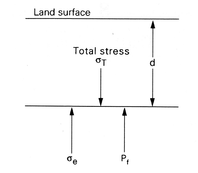
Figure 5.1 Total stress, effective stress, and fluid pressure on a horizontal plane located at depth d below the land surface/water table in a one-dimensional, fluid-saturated geologic medium.
In general, one of the principal stresses will be nearly vertical, at least in regions with gentle topography. The other two principal stresses must thus be nearly horizontal. In a normal-faulting environment the greatest principal stress, σ1, is vertical, and hydraulic fracturing will occur in (sub)vertical planes that are orthogonal to the least principal stress, σ3 (Figure 5.2). In the (more common) reverse- or thrust-faulting environment, σ1 is horizontal and (sub) horizontal fracturing will indeed tend to occur at fluid pressures close to the total overburden pressure (e.g., Hubbert and Willis, 1957). To avoid possible confusion in terminology, we should note that in rock mechanics the term hydrostatic is often used to denote the conditions σ1 = σ2 = σ3. Moreover, because differential pressures are needed to cause deformation, the “hydrostatic” component of stress, (σ1 = σ2 = σ3)/3, is sometimes subtracted from the principal stress to define the deviatoric stresses. Here, we will continue to use hydrostatic only to denote fluid-pressure conditions such that Pf ~ρw gd.
-25-
The concept of effective stress is relatively intuitive in one dimension (Figure 5.1) but can readily be extended to three dimensions, because the fluid pressure at a particular depth or location acts equally on any arbitrary oriented plane. The effective stress in each of the principal-stress directions can thus be defined as σ1 – Pf , σ2 – Pf , and σ3 – Pf . In two or three dimensions, stress is actually a tensor, like hydraulic conductivity or permeability, but we will assume that our coordinate axes are aligned with the principal stress directions (e.g., σ11) so that the off-diagonal terms of the tensor (e.g., σ22) become zero.

Figure 5.2 (a) Relation between principal stresses and fractures in a sample brought to failure in a triaxial test and (b) representation of the failure conditions on a Mohr diagram.
-26-
Some controversies have surrounded this rather simple concept of effective stress. By the 1970s it was generally accepted that an effective normal stress component would have the form σi – APf , where A is some coefficient, but there was vigorous debate regarding the correct value of A. Empirical data show that A is indistinguishable from 1 [1,p.215-218].