

1_c034195
.pdfDownloaded by 94.180.100.60 on November 25, 2018 | http://arc.aiaa.org | DOI: 10.2514/1.C034195
JOURNAL OF AIRCRAFT
Vol. 54, No. 5, September–October 2017
Aeroelastic Optimization of High-Speed Tiltrotor Wings with Wing Extensions and Winglets
Sandilya Kambampati and Edward C. Smith†
The Pennsylvania State University, University Park, Pennsylvania 16802
DOI: 10.2514/1.C034195
Tiltrotors can experience an aeroelastic instability called whirl flutter, which is characterized by highly coupled wing–rotor vibrations, which are catastrophic in nature and limit the maximum speed of the aircraft. In this paper, an optimization study aimed at improving the whirl flutter speed of a tiltrotor equipped with a wing extension and a winglet is presented. Parametric studies are conducted on an aeroelastic model of a rotor mounted on a cantilevered wing with an extension and a winglet. The parameters that are investigated are stiffness, structural taper, composite couplings, extension sweep, and winglet cant angle. It is found that, when the wing has a structural taper and is equipped with a wing extension and a winglet, the whirl flutter speed can be increased by 15%. The parametric study is followed by an optimization study to determine the optimal combinations of these parameters that maximize whirl flutter speed. Genetic algorithms are used for the optimization process. Upper and lower bounds are placed as constraints on the design variables. It is shown that the optimized design has a flutter speed of 22% (65 kt) more than the baseline.
|
|
Nomenclature |
A |
= |
area |
A |
= |
airfoil lift-curve slope |
c |
= |
chord |
cd |
= |
drag coefficient |
cl |
= |
lift coefficient |
dex |
= |
extension aft offset |
EIb |
= wing beamwise bending stiffness |
|
EIc |
= wing chordwise bending stiffness |
|
e= chordwise distance from the aerodynamic center of the airfoil to the elastic axis
GJ |
= |
wing torsional stiffness |
Icg |
= element inertia per unit length |
|
Kbt |
= wing beamwise bending–torsion coupling |
|
Kct |
= wing chordwise bending–torsion coupling |
|
L |
= lift; wing element length |
|
m |
= |
elemental mass |
p |
= |
blade torsion angle |
p0, p1S, p1C |
= blade torsion degrees of freedom |
|
R |
= |
rotor radius |
r |
= rotor blade radial coordinate |
|
Sα |
= element first mass moment per unit length |
|
U |
= |
freestream velocity |
v= wing chordwise motion degrees of freedom
w= wing beamwise motion degrees of freedom
xP |
= pylon translational degrees of freedom |
|
yP |
= |
pylon translational degrees of freedom |
zP |
= |
pylon translational degrees of freedom |
α= angle of attack
αx, αy, αy |
= pylon yaw, pitch, and rotational degrees of |
|
freedom, respectively |
β= blade flap angle
Presented as Paper 2015-1415 at the 56th AIAA/ASCE/AHS/ASC Structures, Structural Dynamics, and Materials Conference, Kissimmee, FL, 5–9 January 2015; received 25 August 2016; revision received 20 December 2016; accepted for publication 4 February 2017; published online Open Access 15 May 2017. Copyright © 2017 by the American Institute of Aeronautics and Astronautics, Inc. All rights reserved. All requests for copying and permission to reprint should be submitted to CCC at www. copyright.com; employ the ISSN 0021-8669 (print) or 1533-3868 (online) to initiate your request. See also AIAA Rights and Permissions www.aiaa.org/ randp.
*Graduate Research Assistant, Aerospace Engineering; suk263@psu.edu. Student Member AIAA.
†Professor, Aerospace Engineering; ecs5@psu.edu. Senior Member AIAA.
βp |
= |
rotor precone angle |
β0, β1S, β1C |
= |
blade flap degrees of freedom |
γ= lock number
ζ= blade lag angle; modal damping ratio
0, ζ1S, ζ1C = blade lag degrees of freedom
Λ= wing and extension sweep angleζ
λt |
= wing structural taper |
ρ= freestream density
σ= stress, lb∕in:2; blade geometric solidity
ϕ= wing torsion motion degrees of freedom
ψ= azimuth angle
Ω= rotor rotation speed
ω= modal frequency
ωθ |
= |
blade torsion frequency |
_ |
= first derivative with respect to time |
|
|
||
|
= |
second derivative with respect to time |
|
||
I.Introduction
HIGH-SPEED tiltrotors are susceptible to an aeroelastic instability called whirl flutter. Whirl flutter is caused by the whirling motion of the rotor, characterized by highly coupled wing– rotor–pylon modes of vibration. The damping ratios of the coupled vibration modes are dependent on forward speed. At high speeds, the damping ratios can become negative due to destabilizing aerodynamic forces on the rotor, leading to a catastrophe. Therefore, whirl flutter is a major obstacle for tiltrotors in achieving high-speed
flight.
Tiltrotor whirl flutter stability margins can be improved by using composite materials. Parametric studies of wing frequencies, blade frequencies, wing sweep angle, and blade kinematic pitch–flap coupling on whirl flutter, using composite materials, were conducted in [1]. It was shown in [1] that the flutter speed was more dependent on the placement of wing frequencies relative to each other than the placement of wing frequencies relative to rotor frequencies. Specifically, the frequency separation between the beam and torsion frequencies had a greater importance on the flutter stability. Composite tailoring of the wing can improve the aeroelastic stability of wing and chord modes by introducing bending–torsion coupling in the wing [2]. The results in [2] indicated that a negative wing beamwise bending–torsion coupling (wing upward beamwise bending coupled to nosedown torsion) can enhance the stability of the wing beamwise bending mode. A parametric study of wing thickness and composite tailoring on the whirl flutter stability boundary of the V-22 tiltrotor was presented by Popelka et al. in [3]. The thin wing had a thickness of 18%, whereas the baseline V-22 had a 23%-thick wing. Reducing the thickness of the wing to 18% decreased the airframe
1718
Downloaded by 94.180.100.60 on November 25, 2018 | http://arc.aiaa.org | DOI: 10.2514/1.C034195
KAMBAMPATI AND SMITH |
1719 |
drag by 10%, but it also decreased the stability boundary by 38 kt due to loss in stiffness. This stability boundary was recovered using composite tailoring. The results showed that the 18%-thick wing, which was tailored using composites and had a redistributed spar cap and spar area, had a stability boundary of 12 kt greater than the baseline 23% wing.
Parametric studies on rotor design to improve whirl flutter stability margins were explored in [4]. Although the study was related to changes in the rotor, a thin composite wing representative of a highspeed tiltrotor was also investigated. The thin wing offered a better aerodynamic performance, but it also had a lower stiffness, which reduced the whirl flutter stability. The wing was assumed to have the same geometry as the XV-15, except that the thickness was reduced from 23 to 15%. The whirl flutter speeds of the 23% wing and 15% wings were 330 and 275 kt, respectively.
Wingtip devices such as wing extensions and winglets are often used in fixed-wing aircraft to reduce induced drag and to increase fuel efficiency [5]. However, winglets have a negative impact structurally on fixed-wing aircraft because they reduce the flutter speed. Experimental results showed that the addition of a winglet reduced the wing flutter dynamic pressure by 12% [6]. This reduction in flutter speed was primarily due to the aerodynamic forces on the winglet rather than the winglet interference effects on the wing or winglet mass. In another study presented in [7], flutter tests were conducted experimentally at Mach numbers ranging from 0.6 to 0.95 on models with a wingtip, a tip with a winglet, and a normal-shaped ballast to simulate the winglet mass properties. The authors of [7] concluded that the winglet effect on flutter was equally a mass effect as well as an aerodynamic effect. The authors of [7] also showed that the effect of winglet stiffness on flutter speed was negligible, and the aerodynamic and inertial effects were major contributors to flutter.
Wing extensions and winglets can also potentially reduce the induced drag on tiltrotor wings, as they operate at relatively high-lift coefficients [8]. Modern tiltrotor wing designs such as the Large Civil Tiltrotor 2 [9] have wing extensions. The effects of wing extensions and winglets on tiltrotor aeroelastic stability were explored in [10,11]. It was shown in [10] that the wing extension can significantly improve the whirl flutter speed. Specifically, a wing extension could improve the stability boundaries of the beam and torsion modes by 70 and 80 kt, respectively. Parametric studies conducted on the winglet in [11] indicated that lowering the cant angle of the winglet improved the beam and torsion mode stability boundaries.
All the aforementioned studies identified various parameters that influenced the whirl flutter characteristics of a tiltrotor. Thus, one can see the need for determining an optimal combination of the key parameters for improving the whirl flutter boundary, and hence the maximum speed of a tiltrotor.
A multidisciplinary optimization procedure was developed in [12] to study the tradeoffs associated with the performance of a high-speed tiltrotor aircraft. The objectives were to maximize the hover figure of merit and high-speed cruise propulsive efficiency while minimizing wing weight, under whirl flutter constraints. The results showed improvements in cruise efficiency while maintaining aeroelastic stability. In more recent studies [13,14], the influence of parametric variations of rotor/wing design variables was explored, such as the rotor flexibility distribution inboard/outboard of the pitch bearing, and the resulting effects on the whirl flutter stability of a tiltrotor. The study identified blade pitch–flap and pitch–lag coupling as the most influential parameters in increasing flutter speed. However, these studies did not explore the effects of structural taper and wingtip devices such as wing extensions and winglets on whirl flutter.
In this paper, an optimization study to improve the whirl flutter speed of a tiltrotor equipped with a wing extension and a winglet is presented. An aeroelastic model that predicts the whirl flutter characteristics of a tiltrotor is developed. Parametric studies are conducted to study the influence of key parameters such as structural taper, composite coupling, and wingtip device planform variables on whirl flutter. We identify that the structural taper, in combination with the wing extension, plays a key role in improving the beam mode damping. The parametric studies are followed by an optimization study aiming at improving the whirl flutter speed. The design
variables are wing parameters (stiffness, composite coupling, structural taper), wing extension, and winglet parameters (stiffness, sweep, and cant angle). The genetic algorithm (GA), which is a nongradient-based search method, is used for the optimization [15]. The advantage of using the GA in multiobjective problems is that it often results in multiple optimal solutions. We show that the optimization helps improve the whirl flutter speed by 22% (65 kt).
II.Aeroelastic Model
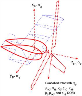
An aeroelastic model consisting of a three-bladed gimballed rotor and pylon mounted on a cantilevered wing with an extension and a winglet is developed (see Fig. 1). The rotor blades undergo rigid flap β, lag ζ, and torsion p motions. The elastic blade modes (which are needed for a more accurate representation of rotors) are not included in this analysis. The pylon has three translational degrees of freedom (xP, yP, zP) and three rotational degrees of freedom (αx, αy, αz), which are coupled with the wing bending and torsion motions (w, v, ϕ). In other words, the wing motion affects the rotor motion, and the resulting rotor aerodynamic and inertial forces influence the wing motion. This model is built, based on the model presented in [10]. However, the authors of [10] did not include the rotor blade torsion degrees of freedom (DOFs) in their analysis. This model is improved by adding in the blade torsion p degrees of freedom in the present analysis. The details of this aeroelastic model are described in the following sections.
A. Rotor and Pylon Model
Consider the three-bladed rotor on a rigid pylon as illustrated in Fig. 1. The pylon motion at the pivot point is assumed to have six degrees of freedom: three translational and three rotational. The translational degrees of freedom of the pylon are xP, yP, and zP, which are the vertical, lateral, and longitudinal motions, respectively; and the rotational degrees of freedom of the pylon are αx, αy, and αz, which represent the pylon yaw, pitch, and roll motions, respectively. The equations dictating the coupled motion of the rotor and pylon [16–18] canbe written in the following matrix form:
|
|
(1) |
MRXR CRXR KRXR FR |
||
where XR is the vector containing the DOFs of the rotor and pylon. The expressions for MR, CR, and KR can be found in [19].
Fig. 1 Aeroelastic model of rotor wing and wing extension.
Downloaded by 94.180.100.60 on November 25, 2018 | http://arc.aiaa.org | DOI: 10.2514/1.C034195
1720 |
KAMBAMPATI AND SMITH |
B. Wing and Wing Extension Model
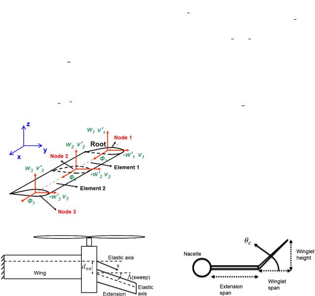
The wing and wing extension are structurally modeled by using the finite element method and include beamwise w, chordwise v, and torsion ϕ DOFs. The beamwise bending and chordwise bending are modeled using piecewise cubic polynomial shape functions, and torsion is modeled using piecewise linear shape functions. A schematic of the finite element discretization of the wing into two elements and three nodes is shown in Fig. 2. From Fig. 2, one can see that each node has five DOFs: w1 and w10 correspond to the beamwise bending DOFs, v1 and v10 correspond to the chordwise bending DOFs, and ϕ is the torsion DOF.
1. Structural Model
The wing spar is assumed to be made of composite materials that allow bending–torsion coupling. The composite box beam stiffness matrix relating the moments and the curvatures is given by
where w, w0, and ϕ are the continuous DOFs of the wing; and Λ is the wing sweep.
Applying the Euler–Lagrange equations for the strain and kinetic energies of the wing yields the following set of equations for each element:
|
|
|
(5) |
MW XW CW XW KW XW FW |
|||
where
XW w1 v1 ϕ1 v10 w10 w2 v2 ϕ2 v20 w20
is the vector containing the DOFs corresponding to the wing; and MW , CW , and KW are the mass, damping, and stiffness matrices of the wing, respectively. The detailed derivation of the wing modeling, as well as the expressions for MW, CW , and KW , can be found in [19].
C. Winglet Model
8 My |
9 |
2 EIb |
0 |
Kbt |
38 w0 0 |
9 |
|
The winglet is assumed to be rigid, and it is connected to the wing |
||||
< Mz |
= |
0 |
EIc |
Kct |
5 |
< v0 0 |
= |
(2) |
extension tip. The winglet is canted by an angle θc as shown in Fig. 4. |
|||
: |
Mϕ |
; |
4 Kbt |
Kct |
GJ |
: |
ϕ 0 |
; |
|
The detailed derivation of the winglet model can be found in [10]. |
||
|
|
|
|
|
|
|
The wing motion causes a perturbation in the angle of attack as |
|||||
where EIb, EIc, and GJ are the beamwise, chordwise, and torsional |
seen by the winglet. The effective angle of attack can be written as |
|||||||||||
αeff ϕwl − wwl∕V |
|
|||||||||||
stiffnesses, respectively. Kbt and Kct are the beamwise and chordwise |
(6) |
|||||||||||
bending–torsion coupling stiffnesses, respectively. |
|
|
|
|
||||||||
2. Aerodynamic Model
The wing and extension are modeled with sweep Λ. The extension is modeled with an aft offset dex, which is the distance between the aerodynamic centers of the wing and extension at the nacelle (see Fig. 3). The quasi-steady lift approximation can now be written as
L |
1 |
ρV2clααeff c |
(3) |
2 |
where ρ is the density, V is the velocity of the aircraft, clα is the lift-curve slope of the wing, c is the wing chord, and
αeff α0 ϕ cos Λ − |
w |
|
ϕ |
dex x sin Λ − e − w0 sin Λ (4) |
|
|
|||
U |
U |
where wwl is the velocity of the wind as seen by the winglet, and ϕwl is the structural twist of the winglet. The expressions for wwl and ϕwl are as follows:
wwl w2 cos θc |
(7) |
ϕwl ϕ2 cos θc v20 sin θc |
(8) |
and the subscript 2 indicates the DOF of the node at which the winglet is added to the wing extension.
The sectional lift generated by the winglet due the effective angle of attack is given by
Lwl |
1 |
ρV2cclααeff |
(9) |
2 |
The sectional lift is computed numerically and is added to the finite element model of the wing at the nodes where the wing extension is attached to the winglet.
D. Coupling Rotor and Wing Systems
The equations of motion for the coupled motions involving the rotor and wing can be written as a set of standard second-order differential equations:
|
(10) |
MX CX KX F |
where X is vector containing all the degrees of freedom; and M, C, and K are the mass, damping, and stiffness matrices, respectively. The frequency and damping characteristics of the system can be
Fig. 2 Schematic of the finite element model of the wing [10]. calculated from the eigenvalues λi of Eq. (1). The frequency ωi and damping ζi are given by
Fig. 3 Schematic of a swept extension with an offset.
Fig. 4 Schematic showing winglet cant angle.
KAMBAMPATI AND SMITH |
1721 |
Table 1 Important properties of Gen-3a and Gen-3b
Item |
Gen-3a |
Gen-3b |
Number of blades N |
3 |
3 |
Radius R, in. |
8.05 |
8.55 |
Lock number γ |
3.22 |
3.70 |
Solidity σ |
0.102 |
0.096 |
Rotor speed Ω, rpm |
2000 |
2000 |
Pitch–flap coupling KP |
−1.09 |
−1.09 |
Twist rate |
0 |
−25 deg ∕R |
Wing semispan, in. |
14.35 |
14.35 |
Wing beamwise frequency ωb, Hz |
5.316 |
5.316 |
Wing chordwise frequency ωc, Hz |
7.526 |
7.526 |
Wing torsional frequency ωt, Hz |
26.49 |
26.49 |
|
|
|
ωi Im λi
ζi Reλ λi
j ij
Downloaded by 94.180.100.60 on November 25, 2018 | http://arc.aiaa.org | DOI: 10.2514/1.C034195
A particular mode becomes unstable when the damping of that particular mode goes to zero. The lowest forward speed at which the damping of any of the modes is zero is defined as the whirl flutter speed.
E. Experimental Validation
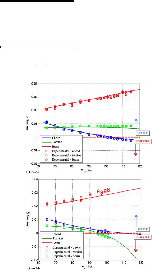
Semispan wind-tunnel tiltrotor whirl flutter models are designed and tested in the Pennsylvania State Hammond Low-Speed Wind Tunnel for validating the present analysis. The models were mounted onto a load cell; and they were excited at the beam, chord, and torsion frequencies at different wind-tunnel speeds. The corresponding time history of the root forces and bending moments were analyzed to compute damping ratios at different wind-tunnel speeds. The
(11)
properties of the wing and rotor for two particular wind-tunnel models, titled Gen-3a and Gen-3b, are tabulated in Table 1. The experimental and predicted damping ratios of the wing modes (beam,
(12)chord, and torsion modes) for Gen-3a and Gen-3b are shown in Fig. 5. We can see from Fig. 5 that the predictions match well with the
Fig. 5 Predicted and measured damping versus tunnel speed.
Downloaded by 94.180.100.60 on November 25, 2018 | http://arc.aiaa.org | DOI: 10.2514/1.C034195
1722 |
KAMBAMPATI AND SMITH |
experiments. The complete details of the validation study can be found in [20].
III.Parametric Studies
In this section, parametric studies are conducted on various key parameters that influence whirl flutter. The baseline model for our study is the Bell XV-15 rotor on a soft torsion wing with an extension and a winglet. The important rotor, wing, extension, and winglet parameters of the baseline model are tabulated in Tables 2 and 3 (from [10]). The inputs for the finite element analysis of the wing are given in Table 4, where Le is the element length; Sα and Icg are the first and second mass moments of inertia, respectively; m is the mass per length; Λ is the wing forward sweep angle; e is the distance of wing elastic axis from the aerodynamic center; and EI0b, EI0c, and GJ0 are the beamwise stiffness, chordwise stiffness, and torsional stiffness, respectively. The fundamental frequencies (beam, chord, and torsion) of the baseline wing, computed at 300 kt, are shown in Fig. 5.
A. Rotor Blade Torsion DOF
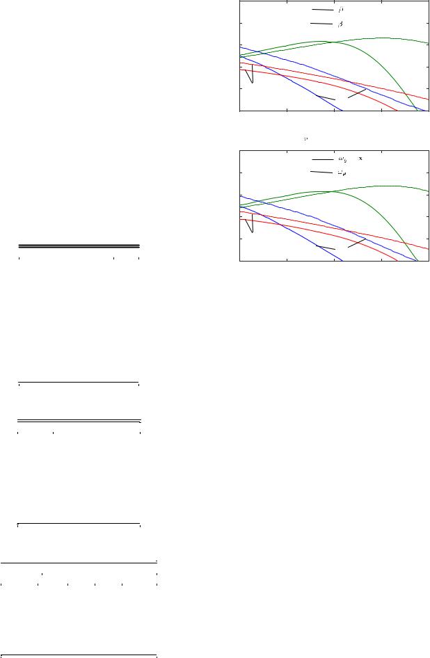
The frequency of the blade torsion motion ωθ, in combination with the blade precone angle βp, can be destabilizing to whirl flutter. The influence of βp on the damping of wing modes is shown in Fig. 6a for
Table 2 Rotor and wing properties
Parameter |
Value |
Rotor |
|
Number of blades |
3 |
Radius R, ft |
12.5 |
Lock number |
3.83 |
Solidity |
0.089 |
Blade flapping inertia, slug∕ft2 |
105 |
Lift-curve slope |
5.7 |
Pitch–flap coupling |
−0.268 |
Tip speed, ft∕s |
600 |
Rotational speed Ω, rad∕s |
48 |
Wing (semispan) |
|
Span (L∕R) |
1.333 |
Chord (c∕R) |
0.413 |
Mast height (h∕R) |
0.342 |
|
|
Table 3 Wing extension and
|
|
winglet properties |
|
|
||
|
|
|
|
|
||
|
|
|
|
|
||
|
Parameter |
Value |
|
|
||
|
Wing extension |
|
|
|
|
|
|
Length |
4.55 ft (27% of wing span) |
||||
|
Chord |
5.16 ft (100% wing chord) |
||||
|
Stiffness |
50% of wing |
|
|
||
|
Inertia |
|
50% of wing |
|
|
|
|
Winglet |
4.55 ft 27% of wing span |
||||
|
Length |
|||||
|
Chord |
2.58 ft 50% wing chord |
||||
|
Cant angle |
90 deg |
|
|
||
|
Inertia |
|
25% of wing |
|
|
|
|
|
|
||||
|
|
|
|
|
|
|
|
Table 4 Wing properties used for finite |
|||||
|
|
element analysis |
|
|
||
|
|
|
|
|
|
|
|
|
|
|
|
|
|
|
|
|
Element number |
|
|
|
|
|
1 (root) |
2 |
3 |
4 (pylon) |
|
Le, ft |
4.55 |
4.55 |
4.55 |
3 |
||
Icg, slug∕ft |
1.0 |
1.0 |
1.0 |
63.3cos2Λ |
||
Sα, slug |
0.05 |
0.05 |
0.05 |
9.09 cos Λ |
||
m, slug∕ft |
1.0 |
1.0 |
1.0 |
14.54 |
||
EIb0 , lb∕ft2 |
3.13e7 |
3.13e7 |
3.13e7 |
3.13e7 |
||
EIc0, lb∕ft2 |
8.48e7 |
8.48e7 |
8.48e7 |
8.48e7 |
||
GJ0, lb∕ft2 |
0.81e7 |
0.81e7 |
0.81e7 |
0.81e7 |
||
e∕c |
0.051 |
0.051 |
0.051 |
0.0 |
||
|
|
|
|
|
|
|
|
0.1 |
|
p = 0° |
|
|
|
|
|
|
|
|
|
0.08 |
|
p = 2.5° |
|
|
Ratio |
0.06 |
|
|
Torsion |
|
Damping |
0.04 |
|
|
|
|
|
|
|
|
|
|
|
0.02 |
Chord |
|
|
|
|
|
|
Beam |
|
|
|
0 |
250 |
300 |
350 |
400 |
|
200 |
V, kt
a) Effect of rotor precone ( )
)
|
0.1 |
|
= |
/revolution |
|
|
|
|
|
||
|
0.08 |
|
= 4.8 /revolution |
|
|
Ratio |
0.06 |
|
|
Torsion |
|
Damping |
0.04 |
|
|
|
|
|
|
|
|
|
|
|
0.02 |
Chord |
|
|
|
|
|
|
Beam |
|
|
|
0 |
250 |
300 |
350 |
400 |
|
200 |
||||
V, kt
b) Effect of blade torsion frequency ( )
)
Fig. 6 Damping of wing modes for different values of βp and ωθ vs airspeed V.
βp 0 and 2.5 deg (baseline). From Fig. 6a, one can see the destabilizing effect the precone on wing damping. The influence of ωθ on the damping of wing modes is shown in Fig. 6b for ωθ 4.8∕revolution (baseline) and no torsion (ωθ ∞), where one can see the destabilizing nature of the blade torsional motion. The results from the Figs. 6a and 6b, which show the destabilizing nature of βp and ωθ, are consistent with previous studies [17].
B. Structural Taper
The structural taper and wing extension are design features in the NASA Large Civil Tiltrotor 2 [21]. The beam mode damping is increased from 4.5 to 6% when the taper ratio is changed from 1 to 0.1. This result has motivated us to investigate the effects of structural taper upon our model. In the present analysis, structural taper is implemented by decreasing the beamwise and chordwise stiffnesses linearly with span, such that
EIbtip∕EIbroot EIctip∕EIcroot λt 0.5
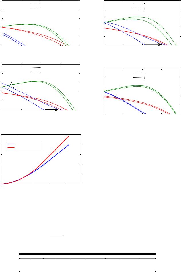
In Fig. 7a, the damping of the wing modes is plotted for an untapered wing and a tapered wing, without the wingtip devices. The whirl flutter speed is increased slightly, by approximately 10 kt, for the tapered wing. With the wing wingtip devices on, the whirl flutter speed is increased by 45 kt (see Fig. 7b) for the tapered wing.
Structural taper increases the tip deflection. The efficiency of the wing extensions in improving the beam mode damping increases with tip deflection. The mode shapes with and without taper (normalized by the root bending curvature) are plotted in Fig. 8, where one can see that the tapered wing has a higher tip deflection than the untapered wing. Thus, one can conclude that structural taper, when combined with wingtip devices, can help increase the beam mode damping.
The frequencies of the wing fundamental modes are shown in Table 5. As expected, the tapered wing vibrates at lower frequencies than the baseline untapered wing.
Downloaded by 94.180.100.60 on November 25, 2018 | http://arc.aiaa.org | DOI: 10.2514/1.C034195
KAMBAMPATI AND SMITH |
1723 |
|
0.1 |
|
With Structural Taper |
|
|
0.1 |
|
|
= 0.2 |
|
|
|
|
|
|
|
|
|
bt |
|
|||
|
0.08 |
|
No Structural Taper |
|
|
0.08 |
|
bt |
= 0 |
|
|
Ratio |
0.06 |
|
|
|
|
Ratio |
0.06 |
|
|
Torsion |
|
Damping |
|
|
Torsion |
|
|
Damping |
|
|
|
|
|
|
|
|
|
0.04 |
|
|
|
|
|||
|
|
|
|
|
|
|
|
|
|
||
|
0.04 |
|
|
|
|
|
|
|
|
|
|
|
|
|
|
|
|
|
|
Chord |
|
|
|
|
0.02 |
Beam |
Chord |
|
|
|
0.02 |
|
|
|
|
|
|
|
|
|
|
|
|
Beam |
|
||
|
|
|
|
|
|
|
|
|
|
||
|
0 |
250 |
300 |
350 |
400 |
|
0 |
250 |
300 |
350 |
400 |
|
200 |
|
200 |
||||||||
|
|
|
V, kt |
|
|
|
|
|
V, kt |
|
|
a) Without wing extension and winglet |
Fig. 9 Effects of beamwise bending–torsion composite coupling ϵbt on |
|
wing modes damping (beam, chord, and torsion) with airspeed V. |
|
0.1 |
|
With Structural Taper |
|
|
|
|
|
|
|
|
|
|
|
|
|
0.1 |
|
|
|
|
||
|
|
|
|
|
|
|
|
|
= 0.2 |
|
|
|
0.08 |
|
No Structural Taper |
|
|
|
|
ct |
|
||
DampingRatio |
|
Beam |
|
|
|
|
0.08 |
|
ct |
= 0 |
|
0.06 |
|
|
|
RatioDamping |
|
|
|
|
|
||
|
Chord |
|
|
|
|
Chord |
|
|
|||
|
|
|
|
0.06 |
|
|
|
||||
|
|
|
Torsion |
|
|
|
|
|
Torsion |
|
|
|
|
|
|
|
|
|
|
|
|
||
|
0.04 |
|
|
|
|
|
|
|
|
|
|
|
|
|
|
|
|
|
|
|
|
|
|
|
|
|
|
|
|
|
0.04 |
|
|
|
|
|
0.02 |
|
|
|
|
|
|
|
|
|
|
|
|
|
|
|
|
|
0.02 |
|
|
|
|
|
0 |
250 |
300 |
350 |
400 |
|
|
|
Beam |
|
|
|
200 |
|
0 |
|
|
|
|
||||
|
|
|
V, kt |
|
|
|
200 |
250 |
300 |
350 |
400 |
b) With wing extension and winglet |
V, kt |
Fig. 7 Effects of structural taper on wing modes damping vs airspeed V. |
Fig. 10 Effects of chordwise bending–torsion composite coupling ϵct on |
|
wing modes damping (beam, chord, and torsion) with airspeed V. |
1 |
|
|
|
|
|
|
0.8 |
|
No Structural taper |
|
|
|
|
|
|
2:1 Structural taper |
|
|
|
|
0.6 |
|
|
|
|
|
|
w (ft) |
|
|
|
|
|
|
0.4 |
|
|
|
|
|
|
0.2 |
|
|
|
|
|
|
0 |
0 |
5 |
10 |
15 |
20 |
25 |
Span (ft)
Fig. 8 Mode shapes (beamwise deflection w vs spanwise location) with and without structural taper.
C. Composite Coupling
Composite tailoring of the wing can introduce coupling between bending and torsional modes. Note that ϵbt and ϵct are the nondimensional values of the bending–torsion coupling of the beam and chord modes, respectively, defined by
Kbt |
|
|
Kct |
|
ϵbt pEIbGJ |
; |
ϵct |
pEI GJ |
(13) |
|
|
|
c |
|
Figure 9 shows the effect of beamwise bending–torsion coupling on the bending and torsion modes. Positive values of ϵbt bring the frequencies of the beam and torsion modes closer (see Table 5) and stabilize the beam mode while destabilizing the torsion mode.
Figure 10 shows the effect of chordwise bending–torsion coupling. Positive values of ϵct separate the frequencies of chord and torsion modes (see Table 5), and they stabilize the chord mode while destabilizing the torsion mode. These results are that of a structurally untapered wing, and they are consistent with previous studies [2,10].
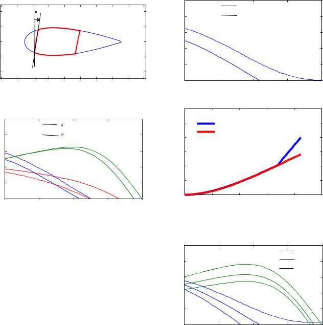
D. Rotated Wing Spar
Rotating the wing spar about the span by a few degrees introduces an elastic coupling between the beam and chord modes. The moment-curvature relationship of a wing spar rotated by an angle θ1 (see Fig. 11) is given by the following:
2Mx |
3 |
|
2 EIbcos2θ1 EIcsin2θ1 |
EIc −EIb cosθ1 sin θ1 |
0 |
3 |
|
6My |
7 |
6 |
EIc −EIb cos θ1 sin θ1 |
EIccos2θ1 EIbsin2θ1 |
0 |
7 |
|
6 |
7 |
|
6 |
|
|
|
7 |
4Mz |
5 |
|
4 |
0 |
0 |
GJ |
5 |
2w00 z |
3 |
|
|
|
|||
×6 v00 z |
7 |
|
(14) |
||||
6 |
|
|
|
7 |
|
|
|
45
ϕ0 z
Table 5 Frequencies of the fundamental wing modes (in radians per second) when certain parameters are modified from their baseline values
|
Baseline |
λt 0.5 |
ϵbt 0.2 |
ϵct 0.2 |
θtw 10 |
deg |
dex 1 ft |
Λ 30 deg |
kex 0.002 |
|
|
||||||||
Beam |
16.2 |
15.3 |
17.3 |
16.1 |
16.0 |
|
16.0 |
16.3 |
16.2 |
Chord |
31.0 |
29.5 |
31.0 |
30.6 |
30.7 |
|
31.0 |
31.2 |
31.0 |
Torsion |
43.2 |
42.7 |
41.4 |
43.2 |
43.6 |
|
42.0 |
42.0 |
41.6 |
|
|
|
|
|
|
|
|
|
|
|
|
|
|
|
|
|
|
|
|
Downloaded by 94.180.100.60 on November 25, 2018 | http://arc.aiaa.org | DOI: 10.2514/1.C034195
1724 |
KAMBAMPATI AND SMITH |
Schematic of the wing cross section
|
10 |
1 |
|
|
|
|
|
|
|
|
|
|
|
|
|
|
|
|
5 |
|
Torque box |
|
|
|
|
|
inches |
|
|
|
|
|
|
|
|
0 |
|
|
|
|
|
|
|
|
|
|
|
|
|
|
|
|
|
|
-5 |
|
|
|
Skin |
|
|
|
|
|
|
|
|
|
|
|
|
|
-10 |
|
|
|
|
|
|
|
|
-30 -20 -10 |
0 |
10 |
20 |
30 |
40 |
50 |
60 |
in
Fig. 11 Schematic of the wing and torque box when rotated by θ1.
|
0.1 |
|
|
|
|
|
|
|
|
|
1 = -10° |
|
|
|
0.08 |
|
|
1 = 0° |
|
|
Ratio |
0.06 |
|
|
|
Torsion |
|
Damping |
|
|
|
|
|
|
0.04 |
|
Beam |
|
|
|
|
|
|
|
|
|
||
|
|
|
|
|
|
|
|
0.02 |
Chord |
|
|
|
|
|
|
|
|
|
|
|
|
0 |
|
250 |
300 |
350 |
400 |
|
200 |
|||||
V, kt
Fig. 12 Effects of a rotated main wing spar on wing modes damping vs airspeed V.
|
0.1 |
|
Soft Wing Extension |
|
|
|
|
|
|
||
|
0.08 |
|
Baseline |
|
|
Ratio |
0.06 |
|
|
|
|
Damping |
0.04 |
|
|
|
|
|
|
|
|
|
|
|
0.02 |
Beam |
|
|
|
|
|
|
|
|
|
|
0 |
|
|
|
|
|
200 |
250 |
300 |
350 |
400 |
|
|
|
V, kt |
|
|
a) Damping vs airspeed V
|
3 |
|
|
|
|
|
|
2.5 |
|
Soft wing extension |
|
|
|
|
2 |
|
Baseline |
|
|
|
|
|
|
|
|
|
|
w |
1.5 |
|
|
|
|
|
|
1 |
|
|
|
|
|
|
0.5 |
|
|
|
|
|
|
0 |
5 |
10 |
15 |
20 |
25 |
|
0 |
Span (ft)
b) Mode shape of the beam mode
Fig. 13 Effects of a soft wing extension on damping and mode shape.
where the term EIc − EIb cos θ1 sin θ1 couples the beam and chord modes. Figure 12 shows this coupling effect on an untapered wing. Negative values of θ1 stabilize the beam mode while destabilizing the chord mode. From Table 5, one can see that rotating the spar by θ1 10 deg reduces the beam and chord frequencies while increasing the torsion frequency.
E. Influence of a Soft Wing Extension
The baseline stiffness of the wing extension is essentially rigid, and reducing the stiffness of the wing extension significantly (by a factor of kex 0.002) is found to stabilize the beam mode. Figure 13a shows the damping of the beam mode for the baseline (unstable at 310 kt) and for the soft wing extension (unstable at 395 kt). The mode shapes of this beam mode for the baseline and soft wing extension case are shown in Fig. 13b, where the nondimensional vertical deflection w is plotted against span. The softer wing extension has a higher value of vertical deflection as compared to the baseline value, and hence provides the additional damping required to stabilize the beam mode. The soft wing extension reduces the frequency of the torsion mode, but it has no effect on the beam and chord frequencies (see Table 5).
F. Parametric Study of Extension Sweep Angle and Aft Offset
The wing extension with an aft offset dex and sweep Λ (schematic shown in Fig. 3) can couple the beam and torsion modes, and it has a significant influence on stability. The potential benefits of a swept extension with an aft offset were discussed in [9].
The damping of the beam and torsion modes are plotted in Fig. 14 for different offset values. Introducing an aft offset (dex 1 ft) stabilizes the torsion mode while destabilizing the beam mode. This is because the beam mode shape has a flapup bending and a noseup torsion type of coupling. This implies that the extension, when located aft of the wing, creates a perturbation force in the direction of the wing motion, thus destabilizing the beam mode. Introducing a fore offset (d1ex −1 ft, which is impractical for tiltrotors because the extension
|
0.1 |
|
|
|
dex = 0 ft |
|
|
|
|
|
|
|
0.08 |
|
|
|
dex = 1 ft |
Ratio |
|
|
Torsion |
|
dex = -1 ft |
0.06 |
|
|
|
|
|
Damping |
0.04 |
|
|
|
|
|
|
|
|
|
|
|
0.02 |
|
|
|
|
|
|
|
Beam |
|
|
|
0 |
250 |
300 |
350 |
400 |
|
200 |
V, kt
Fig. 14 Damping of beam and torsion modes for different offset values vs airspeed V.
can be in close proximity to the rotors) can stabilize the beam mode, as it creates a perturbation force opposing the motion of the wing.
Similar results can be obtained for extension sweep (see Fig. 15), where having a sweptback extension (sweep 30 deg) creates a perturbation force in the direction of the wing motion, due to the flapup bending and noseup torsion type of coupling, thus destabilizing the beam mode. Having a sweptforward extension (sweep −30 deg, which is impractical for tiltrotors) creates a perturbation force opposing the wing motion, thus stabilizing the beam mode.
The sweptback extension and an aft offset reduce the torsion frequency (see Table 5), but they have no appreciable effects on the beam frequency.
G. Parametric Study of Winglet Cant Angle
The effects of the winglet cant angle on whirl flutter are studied here (shown in Fig. 16). Decreasing the cant angle increases the
Downloaded by 94.180.100.60 on November 25, 2018 | http://arc.aiaa.org | DOI: 10.2514/1.C034195
KAMBAMPATI AND SMITH |
1725 |
|
0.1 |
|
|
No sweep |
|
|
|
|
|
|
|
|
0.08 |
|
|
Sweep = 30o |
|
|
|
Torsion |
Sweep = -30o |
|
|
Ratio |
|
|
|
||
0.06 |
|
|
|
|
|
Damping |
0.04 |
|
|
|
|
|
|
|
|
|
|
|
0.02 |
|
Beam |
|
|
|
|
|
|
|
|
|
0 |
250 |
300 |
350 |
400 |
|
200 |
V, kt
Fig. 15 Damping of beam and torsion modes for different extension sweep values vs airspeed V.
|
0.1 |
|
|
c = 45° |
|
|
|
|
|
|
|
|
0.08 |
|
|
c = 90° |
|
Ratio |
|
|
Torsion |
|
|
0.06 |
|
|
|
|
|
Damping |
0.04 |
Beam |
|
|
|
|
|
|
|
||
|
Chord |
|
|
|
|
|
|
|
|
|
|
|
0.02 |
|
|
|
|
|
0 |
250 |
300 |
350 |
400 |
|
200 |
V, kt
Fig. 16 Effects of winglet cant angle on the damping of beam and torsion modes vs airspeed V.
Fig. 17 Schematic of the wing, extension, and winglet.
wingspan, which provides additional damping to the wing, increasing the stability of the beam and torsion modes. The chord mode, on the other hand, is not affected by the cant angle.
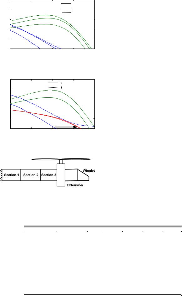
IV. Aeroelastic Optimization
The parametric studies help to understand the influence of many parameters that influence whirl flutter (wing stiffness, taper, composite coupling, and wingtip devices). This motivates an optimization study to improve the aeroelastic stability of the aircraft by identifying the optimal combinations of the aforementioned parameters.
The objective of the aeroelastic optimization is to maximize the whirl flutter speed. The schematic of the wing, extension, and winglet is shown in Fig. 17. The inboard wing is divided into three sections, and the outboard wing is divided into an extension and a winglet. The design variables for the optimization are the wing spar rotation angle, wing structural taper, composite coupling parameters in the wing (ϵbt and ϵct), extension sweep, extension aft offset, and winglet cant angle. The structural taper is implemented by reducing the stiffnesses (EIb, EIc, GJ) in sections 2 and 3 of the wing.
The genetic algorithm is used for the optimization [15]. Constraints are placed on these design variables in the form of upper and lower bounds. The reason for using the GA is that the optimum results are not entirely dependent on the starting design, and the GA often converges to the global minimum, as opposed to gradient-based algorithms where the optimum solution is usually a local minimum.
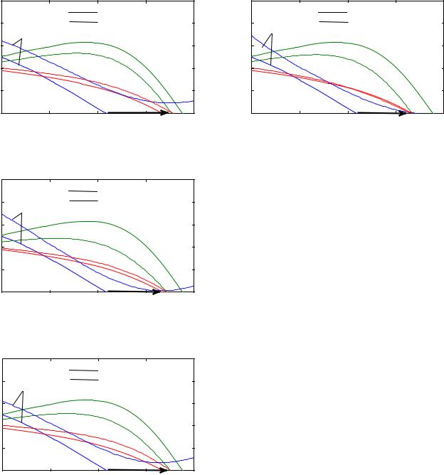
The baseline, bounds, and optimum values of the design variables are tabulated in Table 6 (EI0b, EI0c, and GJ0 are the baseline stiffness values). The damping ratios of the wing modes for the baseline are shown in Fig. 18. The whirl flutter speed of the baseline design is 310 kt (beam mode). Because the GA is used for the optimization, multiple optimal designs can be obtained in the analysis. The parameters of two optimal designs (optimized A and optimized B) are tabulated in Table 6. The optimized-A design has a positive value of ϵct 0.19 while having a spar rotation angle of 2.9 deg. The optimized-B design has a negative value of ϵct −0.05 while having a higher spar rotation angle of 6.3 deg. The optimized-B design has a significant reduction in torsional stiffness, with sections 2 and 3 having less than 65% stiffness of the baseline.
The damping ratios of the wing modes for optimized designs A and B are shown in Figs. 18 and 19, respectively. The flutter speed of the both the optimized designs is 375 kt (65 kt greater than the baseline), even though a few design variables differ significantly from each other in the optimized designs.
A sensitivity study that identifies the key design parameters in the optimization is also presented here. The sensitivity study is conducted by running the optimization again by freezing certain design variables. First, the bending–torsion coupling variables (ϵbt, ϵct) are set to zero. The resulting optimal design variables (optimized C) are tabulated in Table 6. The damping ratios of the wing modes of optimized C are plotted in Fig. 20. From Fig. 20, one can see that the optimum design has an improved flutter speed of 375 kt (a 65 kt increase). These results show that the flutter speed of optimized A and optimized B, which have composite couplings, have the same flutter speed as optimized C,
Table 6 Design variables of baseline, optimized-A, optimized-B, optimized-C, and optimized-D designs
Item |
Minimum/maximum |
Baseline |
Optimized A |
Optimized B |
Optimized C |
Optimized D |
ϵbt |
−0.2∕0.2 |
0 |
−0.05 |
−0.07 |
0 |
−0.1 |
ϵct |
−0.2∕0.2 |
0 |
0.19 |
−0.05 |
0 |
0.13 |
Spar rotation angle, deg |
0∕10 |
0 |
2.9 |
6.3 |
8.6 |
2.3 |
Wing section 2 |
|
|
|
|
|
|
EIb∕EIb0 |
0.5∕1 |
1 |
0.84 |
0.89 |
1 |
0.5 |
EIc∕EIc0 |
0.5∕1 |
1 |
0.84 |
0.89 |
1 |
0.5 |
GJ∕GJ0 |
1 |
1 |
1 |
0.63 |
0.96 |
0.95 |
Wing section 3 |
|
|
|
|
|
|
EIb∕EIb0 |
0.5∕1 |
1 |
0.80 |
0.89 |
0.76 |
0.5 |
EIc∕EIc0 |
0.5∕1 |
1 |
0.80 |
0.89 |
0.76 |
0.5 |
GJ∕GJ0 |
0.5∕1 |
1 |
0.95 |
0.51 |
0.72 |
0.96 |
Extension and winglet |
0∕25 |
|
|
|
|
|
Extension sweep, deg |
0 |
5 |
5 |
5 |
6.4 |
|
Extension aft offset, ft |
0∕4 |
0 |
0 |
0.4 |
0 |
0.53 |
Winglet cant angle, deg |
60∕90 |
90 |
68.7 |
60 |
63.6 |
90 |
|
|
|
|
|
|
|
Downloaded by 94.180.100.60 on November 25, 2018 | http://arc.aiaa.org | DOI: 10.2514/1.C034195
1726 |
KAMBAMPATI AND SMITH |
|
0.1 |
|
|
|
|
|
|
|
Baseline |
|
|
|
0.08 |
|
Optimized |
|
|
|
|
|
|
|
|
Ratio |
Beam |
|
|
|
|
0.06 |
|
Torsion |
|
|
|
Damping |
|
|
|
|
|
0.04 |
|
|
|
|
|
Chord |
|
|
|
|
|
|
|
|
|
|
|
|
0.02 |
|
|
|
|
|
0 |
|
65 kt |
|
|
|
250 |
300 |
350 |
400 |
|
|
200 |
V, kt
Fig. 18 Damping ratios vs airspeed V of baseline and optimized-A designs.
|
0.1 |
|
|
|
|
|
|
|
Baseline |
|
|
|
0.08 |
|
Optimized |
|
|
Ratio |
Beam |
|
|
|
|
0.06 |
|
Torsion |
|
|
|
Damping |
|
|
|
|
|
0.04 |
|
|
|
|
|
Chord |
|
|
|
|
|
|
|
|
|
|
|
|
0.02 |
|
|
|
|
|
0 |
|
50 kt |
|
|
|
|
|
|
|
|
|
200 |
250 |
300 |
350 |
400 |
V, kt
Fig. 21 Damping ratios vs airspeed V of baseline and optimized-D designs.
|
0.1 |
|
|
|
|
|
|
|
|
|
Baseline |
|
|
|
0.08 |
|
|
Optimized |
|
|
Ratio |
Beam |
|
|
|
|
|
0.06 |
|
Torsion |
|
|
||
Damping |
|
|
|
|
||
0.04 |
|
|
|
|
|
|
Chord |
|
|
|
|
|
|
|
|
|
|
|
|
|
|
0.02 |
|
|
|
|
|
|
0 |
|
|
65 kt |
|
|
|
200 |
250 |
300 |
350 |
400 |
|
V, kt
Fig. 19 Damping ratios vs airspeed V of baseline and optimized-B designs.
|
0.1 |
|
|
|
|
|
|
|
Baseline |
|
|
|
0.08 |
|
Optimized |
|
|
Ratio |
Beam |
|
|
|
|
0.06 |
|
Torsion |
|
|
|
Damping |
|
|
|
|
|
0.04 |
|
|
|
|
|
Chord |
|
|
|
|
|
|
|
|
|
|
|
|
0.02 |
|
|
|
|
|
0 |
|
65 kt |
|
|
|
|
|
|
|
|
|
200 |
250 |
300 |
350 |
400 |
V, kt
Fig. 20 Damping ratios vs airspeed V of baseline and optimized-C designs.
which is a much simpler design because it has no composite coupling. Note that the optimized-C design has a higher spar rotation angle of 8.6 deg. Therefore, one can say that higher values of the spar rotation angle are needed when composite coupling is absent in order to stabilize the wing beam mode.
Next, the winglet cant angle is held fixed at 90 deg so that the wingspan is a constant. The resulting optimal design variables (optimized D) are tabulated in Table 6. The damping ratios of the wing modes are plotted in Fig. 21, where one can see that the optimized design has a 50 kt increase in flutter speed. Note that the beamwise and chordwise stiffnesses (EIb, EIc) in sections 2 and 3 of the optimized-D design are reduced by 50%. Therefore, one can say the beamwise and chordwise stiffnesses must be structurally tapered by 50% when the outboard wingspan is held fixed, in order to stabilize the wing beam mode.
The present optimization study focuses on ways to improve the whirl flutter speed, and it can be extended to include other design criteria. For example, adding a wing extension can increase the wing weight, reducing the tiltrotor performance. Introducing wing weight as a constraint in the optimization can keep the wing weight under check. Also, introducing stress constraints at the root, under jump takeoff loads, might regulate the amount of composite coupling that can be introduced in the wing.
V.Conclusions
An aeroelastic model of a rotor and a pylon mounted on a semispan wing with an extension and a winglet is developed. This model is based on the aeroelastic model presented in [10], and it is improved by adding the rotor blade torsion degrees of freedom. Parametric studies of structural taper, composite couplings, stiffness of the wing and wing extension, wing spar rotation angle, and extension and winglet planform variables on whirl flutter are conducted. The parametric study is followed by an optimization study, where the optimal combinations of these parameters that maximize the whirl flutter speed are computed. The following conclusions can be drawn based on this study:
1)The wingtip devices improve the beam and torsion mode stability; however, they do not have a significant influence on the chord mode.
2)Structural taper increases the tip deflection; hence, the wingtip devices are more efficient in increasing the beam mode flutter boundary [by 15% (45 kt)] when the wing has a structural taper. The chord and torsion modes are, however, not affected by structural taper.
3)Introducing bending–torsion coupling in the wing is found to improve the stability boundary of the beam and chord modes (consistent with previous studies).
4)The baseline stiffness used for the extension is found to be essentially rigid, and reducing the stiffness of the extensions significantly from its baseline value stabilizes the beam mode. The softer extension has higher tip deflections, and it provides sufficient damping to stabilize the beam mode.
5)Awing extension, which is swept back or located aft of the wing, can aerodynamically couple the beam and torsion modes. Such an extension destabilizes the beam mode, while stabilizing the torsion mode, if the mode shape of the beam mode has a flapup bending and noseup torsion type of coupling.
6)The optimized design (optimized A) has an improved flutter speed of 22% (65 kt) more than that of the baseline design. The beam mode is the least stable mode in the baseline design, whereas the chord and torsion modes are the least stable modes in the optimized design.
7)The optimization process is performed by setting the bending– torsion composite coupling parameters to zero. The resulting optimum design (optimized C) also has a 22% (65 kt) increase in flutter speed. Thus, maximum gains in flutter speed can be achieved without using composite coupling when the wing has a structural taper and is equipped with wingtip devices.
Downloaded by 94.180.100.60 on November 25, 2018 | http://arc.aiaa.org | DOI: 10.2514/1.C034195
KAMBAMPATI AND SMITH |
1727 |
Acknowledgments
This research is partially funded by the U.S. Government under agreement no. W911W6-06-2-0008. The views and conclusions contained in this document are those of the authors and should not be interpreted as representing the official policies, either expressed or implied, of the U.S. Government. The authors would also like to express their gratitude to Wally Acree at NASA Ames Research Center for technical discussions.
References
[1]Nixon, M. W., “Parametric Studies for Tiltrotor Aeroelastic Stability in Highspeed Flight,” Journal of the American Helicopter Society, Vol. 38, No. 4, 1993, pp. 71–79.
[2]Yang, C., and Xia, P., “Aeroelastic Stability of Wing/Pylon/Rotor Coupled System for Tiltrotor Aircraft in Forward Flight,” Science China Technological Sciences, Vol. 54, No. 10, 2011, pp. 2708–2715.
[3]Popelka, D., Lindsay, D., Parham, T., Berry, V., and Baker, D. J., “Results of an Aeroelastic Tailoring Study for a Composite Tiltrotor Wing,” Journal of the American Helicopter Society, Vol. 42, No. 2, 1997, pp. 126–136.
doi:10.4050/JAHS.42.126
[4]Acree, C., Jr., Peyran, R., and Johnson, W., “Rotor Design Options for Improving XV-15 Whirl-Flutter Stability Margins,” NASA TP-2004- 212262, 2004.
[5]Whitcomb, R. T., “A Design Approach and Selected Wind Tunnel Results at High Subsonic Speeds for Wing-Tip Mounted Winglets,” NASA TN D-8260, July 1976.
[6]Farmer, M. G., “Preliminary Study of Effects of Winglets on Wing Flutter,” NASA TM X-3433, Dec. 1976.
[7]Ruhlin, C. L., Rauch, F., and Waters, C., “Transonic Flutter Model Study of a Supercritical Wing and Winglet,” Journal of Aircraft, Vol. 20, No. 8, 1983, pp. 711–716.
doi:10.2514/3.44933
[8]Cole, J. A., Maughmer, M. D., and Bramesfeld, G., “Aerodynamic Design Considerations for Tiltrotor Wing Extensions and Winglets,” 51st AIAA Aerospace Sciences Meeting Including the New Horizons Forum and Aerospace Exposition, AIAA Paper 2013-1088, 2013.
[9]Acree, C., Jr., “Aerodynamic Limits on Large Civil Tiltrotor Sizing and Efficiency,” 5th Decennial AHS Aeromechanics Specialists’
Conference, The American Helicopter Soc., San Francisco, CA, 2014.
[10]Zhang, J., and Smith, E., “Influence of Aeroelastically Tailored Wing Extensions and Winglets on Whirl Flutter Stability,” 2nd Asian/ Australian Rotorcraft Forum and 4th International Basic Research Conference on Rotorcraft Technology, The Asian/Australian Rotorcraft Forum, Tianjin, PRC, 2013.
[11]Zhang, J., and Smith, E., “Parametric Studies of Wing Extensions and Winglets on Whirl Flutter Stability,” 5th Decennial AHS Aeromechanics Specialists Conference, The American Helicopter Soc., San Francisco, CA, 2014.
[12]McCarthy, T. R., and Chattopadhyay, A., “A Coupled Rotor/Wing Optimization Procedure for High Speed Tilt-Rotor Aircraft,” Journal of the American Helicopter Society, Vol. 41, No. 4, 1996, pp. 360–369. doi:10.4050/JAHS.41.360
[13]Hathaway, E. L., “Active and Passive Techniques for Tiltrotor Aeroelastic Stability Augmentation,” Ph.D. Thesis, Pennsylvania State Univ., State College, PA, 2005.
[14]Paik, J., “The Aeroelastic Stability Improvements of Soft-Inplane Tiltrotors by Active and Passive Approaches,” Ph.D. Thesis, Pennsylvania State Univ., State College, PA, 2009.
[15]Conn, A., Gould, N., and Toint, P., “A Globally Convergent Lagrangian Barrier Algorithm for Optimization with General Inequality Constraints and Simple Bounds,” Mathematics of Computation of the American Mathematical Society, Vol. 66, No. 217, 1997, pp. 261–289. doi:10.1090/S0025-5718-97-00777-1
[16]Johnson, W., Helicopter Theory, Princeton Univ. Press, Princeton, NJ, 1980, pp. 808–813.
[17]Jonhson, W., “Analytical Modeling Requirements for Tilting Proprotor Aircraft Dynamics,” NASA TN D-8013, July 1975.
[18]Johnson, W., “Analytical Model for Tilting Proprotor Aircraft
Dynamics, |
Including Blade |
Torsion and Coupled Bending |
Modes, and |
Conversion Mode |
Operation,” NASA TM-X-62369, |
Aug. 1974. |
|
|
[19]Kambampati, S., “Optimization of Composite Tiltrotor Wings with Extensions and Winglets,” Ph.D. Thesis, Pennsylvania State Univ., State College, PA, 2016.
[20]Costa, G. J., “Design, Fabrication, Test, and Evaluation of Small-Scale Tiltrotor Whirl Flutter Wind Tunnel Models,” M.S. Thesis, Pennsylvania State Univ., State College, PA, 2015.
[21]Acree, C., Jr., and Johnson, W., “Aeroelastic Stability of the LCTR2 Civil Tiltrotor,” AHS Technical Specialists Meeting, The American Helicopter Soc., Dallas, TX, Oct. 2008.