

Неинвазивное измерение насыщения крови кислородом
(технические средства)
Принцип работы пульсоксиметра
For an idealized light absorbing model as shown in Fig.6 The Lambert-Beer law applies. The intensity I of Ihe light transmitted is related to the incident light I0. by:
![]()

 ,
,
![]() (1)
(1)
= [c]=
Assume that there are N layers of absorbers and that the ith absorber layer has concentration ci, thickness di. and extinction coefficient Ext(i,). From equation (1) it follows, at diastole, when there is a maximum of light intensity:

![]()
(2)
![]()
Al systole, ihe maximum of the heartbeat, and under the assumption that only hemoglobin and oxyhemoglobin are active absorbers in the arterial blood, two additional absorbing parts are added in the exponent of equation 2, which yields the minimum of light intensity:
![]()

Полагая:
![]() ,
подставляя I0
из (2), получим:
(3)
,
подставляя I0
из (2), получим:
(3)

wltere [Hb] is the concentration of hemoglobin and [HbO2] is the concentration of oxyhemoglobin. Dividing equation 2 by equation 3 and taking the logarithm yields the absorption of the arterial blood:

 (4)
(4)
where d is the change in the arterial radius (?) (see Fig.7). The definition for the oxygen saturation in pulse oximetry is:

 (5)
(5)
With two light sources (LEDs) of different wavelengths 1 and 2 the arterial expansion d can be eliminated by the following relation, which is called the ratio R:

 (6)
(6)
Thus, the oxygen saturation SpO2 is:

![]()

![]()


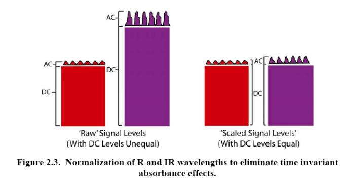

Пример типичной фотоплезмограммы на входе АЦП (инфракрасный канал)


![]()


IR
R

Фильтры
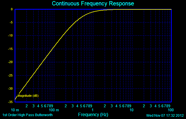
ФВЧ 0.5 Hz:

ФНЧ 5 Hz:


Полосой фильтр 0,5-5 Hz:
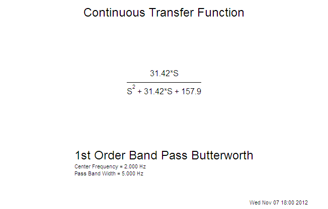

ЛАЧХ

h(t) & k(t)
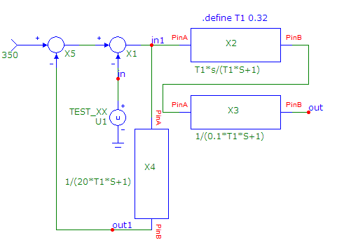
Моделирование в мс-9

Замечание 2.
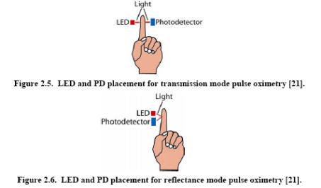
Существует отражательная пдетизмография:


Блок-схема всего пульсоксиметра
![]()
![]()
APPLICATION NOTE 3428 |
Transimpedance Amplifier Buffers Current Transformer |
Abstract: A general-purpose current-measurement system employs a current transformer, ac-coupled to a transimpedance amplifier. About transimpedance and transconductance: The words "transconductance" and "transimpedance" are often used interchangeably. Technically, the terms differ: a transimpedance amp delivers an output voltage that is a function of the input current; conversely, a transconductance amp converts a voltage to a current. Current
transformers are not only a convenient means for current
measurement in many applications, but also provide isolation while
absorbing very little power from the source. The output current
from a current transformer can be converted to voltage with a
suitably valued resistor, but that approach can dramatically
reduce the transformer's high-frequency response.
Transimpedance
amplifiers are a good method for converting current to voltage in
most current-measurement applications. The current source feeds
into the virtual ground of an op amp, and the transimpedance can
be adjusted by changing the value of a single resistor (Figure
1). As
another benefit of this arrangement, the circuit gain for input
offset voltage is no greater than unity.
|
 Figure
1. For resistor values less than 20MΩ,
this simple transimpedance amplifier is acceptable for use with
some current sources.
Resistor
values above 20MΩ
are notoriously difficult to apply. For applications requiring a
transimpedance above 20MΩ,
consider the circuit of Figure
2. The
output voltage-divider adds voltage gain that multiplies the
transimpedance value, enabling effective transimpedances greater
than 200MΩ.
Note that the gain for input offset voltage now equals the
additional voltage gain.
Figure
1. For resistor values less than 20MΩ,
this simple transimpedance amplifier is acceptable for use with
some current sources.
Resistor
values above 20MΩ
are notoriously difficult to apply. For applications requiring a
transimpedance above 20MΩ,
consider the circuit of Figure
2. The
output voltage-divider adds voltage gain that multiplies the
transimpedance value, enabling effective transimpedances greater
than 200MΩ.
Note that the gain for input offset voltage now equals the
additional voltage gain.
 Figure
2. Additional voltage gain in this circuit (vs. that of Figure 1)
provides effective transimpedances greater than 200MΩ.
These
forms of the transimpedance amplifier are useful for inputs that
closely resemble an ideal current source, like, for example, a
photo-diode preamplifier. These forms, however, are not suitable
for use with a current transformer. A current transformer is
similar to an ideal current source, but its source impedance goes
to zero at DC. (True current sources exhibit infinite impedance at
all frequencies.)
The virtual ground (summing node) at
the op amp's inverting input is not at zero potential, but at a
potential equal to the op amp's input offset voltage. Thus,
connecting a current transformer to the input shorts that summing
node directly to ground, causing the output (VOUT) to equal the
input offset multiplied by the amplifier's open-loop gain. The
output thus saturates in the positive or negative direction,
rendering that approach useless.
The circuit of Figure
3
overcomes this problem by AC-coupling the current transformer to
the transimpedance amplifier. Note that the capacitor value
required depends on the application; capacitor value affects the
low-frequency response, and by resonating with the transfomer
inductance, it can produce output peaks at higher frequencies.
Settling time, which depends on the values of R1 and C1, can be as
much as one second. That behavior can be a problem in systems for
which the amplifier is turned on for short periods only.
Figure
2. Additional voltage gain in this circuit (vs. that of Figure 1)
provides effective transimpedances greater than 200MΩ.
These
forms of the transimpedance amplifier are useful for inputs that
closely resemble an ideal current source, like, for example, a
photo-diode preamplifier. These forms, however, are not suitable
for use with a current transformer. A current transformer is
similar to an ideal current source, but its source impedance goes
to zero at DC. (True current sources exhibit infinite impedance at
all frequencies.)
The virtual ground (summing node) at
the op amp's inverting input is not at zero potential, but at a
potential equal to the op amp's input offset voltage. Thus,
connecting a current transformer to the input shorts that summing
node directly to ground, causing the output (VOUT) to equal the
input offset multiplied by the amplifier's open-loop gain. The
output thus saturates in the positive or negative direction,
rendering that approach useless.
The circuit of Figure
3
overcomes this problem by AC-coupling the current transformer to
the transimpedance amplifier. Note that the capacitor value
required depends on the application; capacitor value affects the
low-frequency response, and by resonating with the transfomer
inductance, it can produce output peaks at higher frequencies.
Settling time, which depends on the values of R1 and C1, can be as
much as one second. That behavior can be a problem in systems for
which the amplifier is turned on for short periods only.
 Figure
3. AC-coupling enables this circuit to tolerate the zero source
impedance (at DC) of a current-transformer input.
The
selection of amplifier in Figure 3 depends on the application, but
it generally requires wide bandwidth, low input offset, and
low-power operation.
This
design idea (#597) appeared in the May '04 issue of Selezione
(Italy).
Figure
3. AC-coupling enables this circuit to tolerate the zero source
impedance (at DC) of a current-transformer input.
The
selection of amplifier in Figure 3 depends on the application, but
it generally requires wide bandwidth, low input offset, and
low-power operation.
This
design idea (#597) appeared in the May '04 issue of Selezione
(Italy).
