

Figure 4.2 – Distribution of compressing forces for our case
4.3.8 The time of heating of windings up to extreme allowable temperature (aluminium – 200оC):
tSC200.1
= 0.79·![]() ,
,
where Usc – voltage of short circuit, %;
Δ – density of current, А/m2.
tSC200.1
= 0.79·![]() = 5.838 > 4.
= 5.838 > 4.
tSC200.2
= 0.79·![]() = 4.45 > 4..
= 4.45 > 4..
5 Calculation of transformer magnetis system
5.1 Design of magnetic system
5.1.1 Design of circuit is plane with laminated magnetic system, which construct is from cold-rolled grain-oriented roll steel of the trademark 3405 with width 30 mm under fig. 8.14.
5.1.2 The sizes of bundle are chosen from the table. 8.3 [1] for the rod with calculated diameter dn=0.16 m. The number of steps in the cross section of the rod are 6, the number of steps in the cross section of the yoke are 5.
5.1.3 The area of cross section of rods’ and yokes’ step figure under the tabl. 8.7, р. 365 [1]:
Aleg =0.01835 m2;
Ayoke = 0.01885 m2;
Vcms = 0.002470 m3.
5.1.4 The active cross section of the rod:
AL = Кfilling · Aleg = 0.97· 0. 01835 = 0.018 m2,
Where Кfiling = 0.97 – under the table. 2.2, р. 77 [1].
5.1.5 The active cross section of the yoke:
AY = Кfilling · Ayoke = 0.97·0. 01885 = 0.018284m2.
5.1.6 The volume of steel of a corner of magnetic system:
Vstcms = Кfilling · Vcms = 0.97·0.002470 = 0.0023959 m3.

Figure 5.1 – The definition of scales of the plane magnetic system
The base sizes of magnetic system and cross section of rod and yoke are shown on fig.5.1
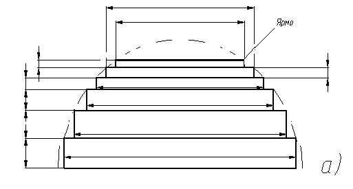
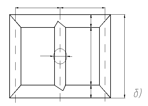
Figure 5.2 – Magnetic system of transformer
а) – cross section of rod and yoke ; b) – base scales of magnetic system .
The sizes of bundles in the cross section of rod and yoke under the
table. 8.3, р. 358 [1]:
№ Of bundle The rod, mm The yoke (in one-half
of cross section ), mm
1 155×20 155×20
2 135×25 135×25
3 120×13 120×13
4 105×8 105×8
5 85×9 85×9
6 55×8 ---
5.1.7 The length of rod:
l = l + (l´O + l´´O),
where l´O =30 mm, l´´O = 30 mm – from tabl. 4.5, 184 [1].
l = 0.5+ (30 + 30)·10-3 = 0.545m.
5.1.8 The distance between axes of rods:
С = D´´2 + a22 = 0.283 + 0.01 = 0.293 m.
5.1.9 Weight of yoke parts, stacked between axes of extreme rods (fig.5.1):
G´yoke = 2·(c –1)·C·AY·γst = 2·(3 – 1)·0.293· 0.018·7650 =164.13 kg,
Where γst – density of transformer steel 7650 kg/m3.
5.1.10 Weight of steel corner of the multi step form of the cross section:
Gcorner = Кfilling·Vcms·γst = 0.97·0.00247 ·7650 =18.32 kg.
5.1.11 Weight of steel in the yoke parts, which are shown on the
fig. 5.1:
G´´yoke = 2·Gcorner = 2·18.32= 36.657 kg.
5.1.12 Weight of steel yoke’s:
Gyoke = G´yoke + G´´yoke = 164.13+ 36.657= 200.787 kg.
5.1.13 Weight of steel rods’ within the limits of a magnetic systems’ window:
G´st = c·AL·LLeg·γst = 3·0.018·0.545·7650 =222.637kg.
5.1.14 Weight of steel in the places of a joint of rod’s and yoke’s bundles:
G´´st = 3·(AL·a1yoke·γst – Gcorner) = 3·(0.018·0.155·7650 –18.32) =-230.968 kg,
Where a1yoke – jointing yoke’s width a1yoke = 0.155m.
5.1.15 Weight of rods’ steel:
Gst = G´st + G´´st =222.637-230.968 = 230.968 kg.
5.1.16 Common weight of steel:
Gsteel = Gyoke + Gst = 200.787+ 230.968 = 431.755 kg.
5.2 Determination of the idling losses
5.2.1 The real induction in the rod:
Вsteel
=
![]() = 1.499T.
= 1.499T.
5.2.2 The real induction in the yoke:
Вyoke
=
![]() = 1.459T.
= 1.459T.
5.2.3 Induction in the area of skew joint:
Вskew
=
![]() = 1.06T.
= 1.06T.
5.2.4 The area of cross section of the area of skew joint:
Askew
=
![]() =
=
![]() 0.018
= 0.025172m2.
0.018
= 0.025172m2.
Specific losses for rods, yokes, area of joint are determine under the tabl. 8.10, р. 376 [1].
For Вleg = 1.499T: PСleg = 0.965Wt/kg; PzlegС=565 Wt/m2.
For Вyoke = 1.459T: Pyoke = 0.9Wt/kg; Pzyoke=535 Wt/m2.
For Вskew = 1.06T: Pskew = 275 Wt/m2.
5.2.5 The losses of idling:
Р0s=
[КРr·Kpz·(Pleg·Gst+Pyoke·G´yoke-6·Pyoke·Gcorner
+
![]() )
+ ΣnЗAsPЗ]·Кpa·Кpp·Кph
where Кpr=1.11
p.380[1];
)
+ ΣnЗAsPЗ]·Кpa·Кpp·Кph
where Кpr=1.11
p.380[1];
Kpr=1.02 p.380[1];
Кpa=1 p.379[1];
Кpp=1.02 tabl. 8.12, р. 380 [1];
Кph=1.01 р. 380 [1];
КPУ=8.58 tabl. 8.13, р. 382 [1].
ΣpЗпЗПЗ = 6·рКОС·Пкос .
ΣnЗAsPЗ =6·0.025·275 = 41.534 Wt
Р0=[1.11·1.02·(0.965·230.968+ 0.9·200.787- 6·0.9·18.329+
+
![]() ·8.58·18.329)
+53.651]· 1.0·1.02·1.01 = 569/1000=0.569 Wt,
·8.58·18.329)
+53.651]· 1.0·1.02·1.01 = 569/1000=0.569 Wt,
5.2.6 Deviation of real idling losses to prescribed (РОЗ):
ΔРО
=
![]() = 5.396% < 7.5%.
= 5.396% < 7.5%.
5.3 Determination of idling current
5.3.1 under the table. 8.17, p. 390 [1] finds specific power of magnetizing:
For Вleg = 1.4999Tl qleg = 1.2; VA/kg; qZLeg = 13500 ВА/м2;
For Вyoke = 1.459Tl: qyoke = 1.15 VA/kg; qZYoke = 11500 ВА/м2;
For Вskew = 1.06Tl qskew =2000ВА/м2.
5.3.2 Idling magnetizing power:
QX
= [Ktr·Ktz·
(qleg·Gst
+ qyoke·G´yoke
- 6·qyoke·Gcorner
+
![]() ·KtУ·Кtrl·Gcorner)
+6·qskew·Askew+
·KtУ·Кtrl·Gcorner)
+6·qskew·Askew+
+ 1·qZLeg·AL + 2·qZYoke·AY] ·Ktyoke·Кtp·Кth,
Where Ktr = 1.49 p.393 [1];
Ktz = 1.01 p.393 [1];
Кtrl = 1.65 table. 8.21, р. 396 [1];
KtY = 1 p.394 [1];
Кtp = 1.04 table. 8.12, р. 380 [1];
Кth = 1.01 p.394[1];
Kty = 27.95 table. 8.20, p.395 [1]
QX = [1.49·1.01· (1.2·230.968+ 1.15·164.13– 6·1.15·18.329 +
+![]() ·27.95·1.65·18.329)
+ 6·2000·0.025 +
·27.95·1.65·18.329)
+ 6·2000·0.025 +
+13500·0.018+2. 11500·0.018]·1·1.04·1.01 = 3118 ВА.
5.3.3 Reactive component of idling current:
IOr
=
![]() = 1.949%.
= 1.949%.
5.3.4 Active component of idling current:
IOA
=
![]() = 3.557*10-4%.
= 3.557*10-4%.
5.3.5 Total idling current:
IO
=
![]() = 1.949%.
= 1.949%.
5.3.6 Deviation of real idling current value to prescribed:
ΔIO
=
![]() = 18.802%< 30%.
= 18.802%< 30%.