

4 Definitions of the characteristics of short circuit
4.1 Definition of losses of the short circuit for LV and HV windings.
Losses of short circuit for LV and HV windings define at the formulae:
4.1.1 General weight of metal of windings:
GМi = Kν·C·Dsri·Wi·Si·103,
Where i – involving to LV and HV windings;
Кν = 8.47 – for aluminums;
С – The number of active rods;
Dsri – average diameter of LV and HV windings, m;
Wi – the number of coils respective winding;
Si – cross section of coil, m2.
- LV winding:
GM1
= 8.47·3·(![]() )·39·1.342.10-4·103
= 23.075kg.
)·39·1.342.10-4·103
= 23.075kg.
- HV winding:
GM2
= 8.47·3·(![]() )
·585· 8.81 ·10-6·103
= 32.503 kg.
)
·585· 8.81 ·10-6·103
= 32.503 kg.
4.1.2 Electrical losses in windings:
Pi = K·Δ2i·GMi,
where К = 12.75·10-12 – for aluminum;
for LV winding:
P1 = 12.75·10-12·(1.721·106)2 .23.075 = 871.255 Wt;
for HV winding:
Р2 = 12.75·10-12· (1.971·106)2 ·32.503 = 1610 Wt.
4.1.3 Weight of metal tapings:
Gtapping.i = Itappingi_star·Stappingi·γal,
where Itappingi_star = 7.5L; Itappingi_delta = 15L;
Stappingi = Si – cross section of coil respective winding, m2.
γal – Density of windings metal (for aluminum – 2700 kg/m3).
for LV winding:
Gtapping1 = 3.75·1.360·10-4·2700 = 1.359 kg.
- for HV winding:
Gtapping2 = 3.75·8.81·10-6·2700 = 0.089 kg.
4.1.4 Losses in tappings:
Ptapping i = K·Δ2i· Gtapping.i,
for LV winding:
Ptapping_loss1 = 12.75·10-12·(1.721·106) 2 ·1.359 = 51.304 Wt.
for HV winding:
Ptapping_loss2 = 12.75·10-12·(1.971·106)2 ·0.089 = 4.419 Wt.
4.1.5 Losses in the tank of transformer:
Рtank_loss = 10·К·SR/1000;
where К = 0.015 – coefficient by the tabl. 4.1, р. 24 [2].
Рtank_loss = 10·0.015·160/1000 = 0.024 Wt.
4.1.6 Losses of the short circuit of transformer:
PSCw = Kd1·P1 + Кd2·P2 + Ptapping_loss1 + Ptapping_loss2 + Рtank_loss ,
where Kd1= Кd2=1.02 coefficient of additional losses (1.02-1.05 by р. 24 [2]).
PSCw = 1.02·871.255 + 1.02·1610+ 51.304 + 4.419 + 0.024 = 2.587 Wt.
4.1.7 Deviation of real losses from prescribed РКЗ:
Δ
PSC
=
![]() =
-2.379 % < 5%.
=
-2.379 % < 5%.
4.2 Voltages of short circuit.
4.2.1. Active component of voltage of short circuit:
VSCa
=
![]() = 1.617%.
= 1.617%.
4.2.2. Reactive component of voltage of short circuit:
VSCr
=
 ,
,
Where
d12 = dn + 2·a01 + 2·a1 + a12 = 0.16 + 2·0·004 +2·0.014 +0.039= 0.234 m,
β
=
![]() = 1.515;
= 1.515;
for the transformers with Sn < 10000 kVA:
аr
= а12 +
![]() = 0.051 m.
= 0.051 m.
Кr = 1 – σ;
σ
=
![]() = 0.048
= 0.048
Кr = 1 – 0.048= 0.952,
VSCr
=
![]() = 4.39 %.
= 4.39 %.
4.2.3 Voltage of short circuit:
VSC
=
![]() = 4.678
= 4.678
4.2.4 Deviation of real VSC from prescribed VSCc:
Δ
VSC
=
![]() = 3.961% < 5%.
= 3.961% < 5%.
4.3. Mechanical forces in windings.
4.3.1 The steady-state current of short circuit:
Isteady_statei
= I1rated·![]() .
.
- LV winding:
ISteady_State1
=
![]() = 4936.463 А ;
= 4936.463 А ;
- HV winding:
ISteady_State2
=
![]() = 329.098А.
= 329.098А.
4.3.2 Impact current of short circuit:
iKMAX
=
![]() Isteady_statei,
Isteady_statei,
where КMAX – factor, which takes into account for the greatest possible aperiodic component of short current circuit.
КMAX
= 1 + е-πVSCa/VSCr
= 1+
![]() = 1.314;
= 1.314;
- for LV winding:
iKMAX1
=
![]() = 9176.173.
= 9176.173.
- for HV winding:
iKMAX2
=
![]() = 611.745А.
= 611.745А.
4.3.3 The radial force, which works on the windings:
Fr = 0.628·(iKMAX·Wi)2·β·KP·10-6,
where Кp = 0.95 by [2] p.27;
W – total number of windings;
- for LV winding:
Fr1 = 0.628·(9176.173 ·39)2 ·1.515·0.95·10-6 = 11575.884 N;
- for HV winding:
Fr2 = 0.628·(611.745 ·585)2 ·1.515·0.95·10-6 =2.605·10-7 N.
Fr the force works on an external winding, trying it to stretch, and on internal, trying it to compress (fig. 4.1).
4.3.4 Total axial force at concentric windings:
F´afi
=
![]() .
.
- LV winding:
F´af1
=
![]() = 5588.663N;
= 5588.663N;
- HV winding:
F´af12
=
![]() = 1257730.534N.
= 1257730.534N.
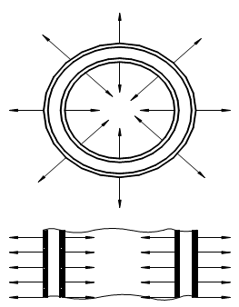
Figure 4.1 – Distribution of radial forces on concentric windings
F´O.C The force is directed downwards in the top half of internal winding and upwards - in the bottom half of winding (compression), and on the contrary in an external winding (stretching).
4.3.5 Axial force working in a place of break of HV, LV winding because of disconnection of regulation windings or coils:
F´´afi
=
![]() ,
,
where lХ = 0 - distance between extreme coils with a current at job of the transformer at the bottom step of regulation of a HV winding. Then:
F´´af1 = 0; F´´af2 = 0.
4.3.6 Pressure on break in the lead of a winding:
σbi
=
![]() ,
,
where W – number of coils of winding, for which is determined force;
П – cross section of one coil, m2.
σb1
=
![]() = 3.52 МPа.
= 3.52 МPа.
σb2
=
![]() = 804.444 МPа.
= 804.444 МPа.
4.3.7 Pressure of compression on basic surfaces:
σСi
=
![]() ,
,
where FСЖ – maximal meaning of compressing axial force;
n = 8 – number of linings on a circle of windings;
а – radial size of a winding, m;
b = 0.04÷0.06 – width of linings , m; assume b=0.04
- LV winding:
σС1
=
![]() = 1.294 МPа
= 1.294 МPа
HV winding:
σС2
=
![]() = 185.659 МPа.
= 185.659 МPа.
σb1, σb2, σС1, σС2 are in permissible limit by tabl.4.1 p.28,[2].
