

BCMSN Exam Certification Guide
.pdf306Chapter 13: Multilayer Switching
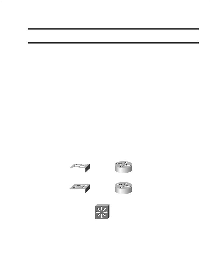
1.Which of the following arrangements can be considered InterVLAN routing?
a.One switch, two VLANs, one connection to a router
b.One switch, two VLANs, two connections to a router
c.Two switches, two VLANs, two connections to a router
d.All of the above
2.How many interfaces are needed in a “router on a stick” implementation for InterVLAN routing among four VLANs?
a.1
b.2
c.4
d.Cannot be determined
3.Which of the following commands configures a switch port for Layer 2 operation?
a.switchport
b.no switchport
c.ip address 192.168.199.1 255.255.255.0
d.no ip address
4.Which of the following commands configures a switch port for Layer 3 operation?
a.switchport
b.no switchport
c.ip address 192.168.199.1 255.255.255.0
d.no ip address
5.Which one of the following interfaces is an SVI?
a.interface fastethernet 0/1
b.interface gigabit 0/1
c.interface vlan 1
d.interface svi 1

“Do I Know This Already?” Quiz 307
6.What information must be learned before CEF can forward packets?
a.The source and destination of the first packet in a traffic flow
b.The MAC addresses of both the source and destination
c.The contents of the routing table
d.The outbound port of the first packet in a flow
7.Which of the following best defines an adjacency?
a.Two switches connected by a common link
b.Two contiguous routes in the FIB
c.Two multilayer switches connected by a common link
d.The MAC address of a host is known
8.Assume CEF is active on a switch. What happens to a packet that arrives needing fragmentation?
a.The packet is switched by CEF and kept intact.
b.The packet is fragmented by CEF.
c.The packet is dropped.
d.The packet is sent to the Layer 3 engine.
9.Suppose a host sends a packet to a destination IP address, and the CEF-based switch does not yet have a valid MAC address for the destination. How is the ARP entry (MAC address) of the next-hop destination in the FIB obtained?
a.The sending host must send an ARP request for it.
b.The Layer 3 forwarding engine (CEF hardware) must send an ARP request for it.
c.CEF must wait until the Layer 3 engine sends an ARP request for it.
d.All packets to the destination are dropped.
10.During a packet rewrite, what happens to the source MAC address?
a.There is no change.
b.It is changed to the destination MAC address.
c.It is changed to the MAC address of the outbound Layer 3 switch interface.
d.It is changed to the MAC address of the next-hop destination.

308Chapter 13: Multilayer Switching
11.What Spanning Tree Protocol is used for fallback bridging?
a.802.1D
b.IBM STP
c.PVST+
d.VLAN-bridge
12.What command can you use to view the CEF FIB table contents?
a.show fib
b.show ip cef fib
c.show ip cef
d.show fib-table
You can find the answers to the “Do I Know This Already?” quiz in Appendix A, “Answers to Chapter ‘Do I Know This Already?’ Quizzes and Q&A Sections.” The suggested choices for your next step are as follows:
■10 or less overall score—Read the entire chapter. This includes the “Foundation Topics,” “Foundation Summary,” and “Q&A” sections.
■11 or 12 overall score—If you want more review on these topics, skip to the “Foundation Summary” section and then go to the “Q&A” section at the end of the chapter. Otherwise, move to Chapter 14, “Router Redundancy and Load Balancing.”

310 Chapter 13: Multilayer Switching
Types of Interfaces
Multilayer switches can perform both Layer 2 switching and interVLAN routing, as appropriate. Layer 2 switching occurs between interfaces that are assigned to Layer 2 VLANs or Layer 2 trunks. Layer 3 switching can occur between any type of interface, as long as the interface can have a Layer 3 address assigned to it.
Like a router, a multilayer switch can assign a Layer 3 address to a physical interface. It can also assign a Layer 3 address to a logical interface that represents an entire VLAN. This is known as a
Switched Virtual Interface.
Configuring InterVLAN Routing
InterVLAN routing first requires that routing be enabled for the Layer 3 protocol. In addition, you must configure static routes or a dynamic routing protocol. These topics are fully covered in the BSCI course.
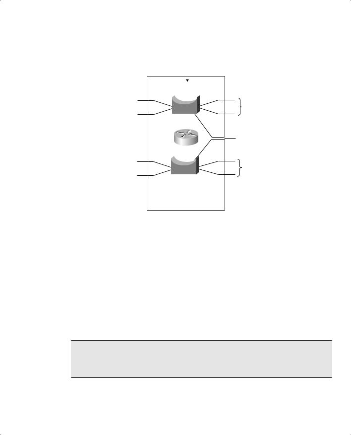
Because a multilayer switch supports many different types of interfaces for Layer 2 or Layer 3 switching, you must define each interface on a switch that will be used. By default, every switch port on a Catalyst 2950, 3550, or 4500 is a Layer 2 interface, whereas every switch port on a Catalyst 6500 (Native IOS) is a Layer 3 interface. If another type or mode is needed, you must explicitly configure it. A port is either in the Layer 2 or Layer 3 mode, depending on the use of the switchport configuraton command. Figure 13-2 shows how the different types of interface modes can be used within a single switch.
Layer 2 Port Configuration
By default, all switch ports on Catalyst 2950, 3550, and 4500 platforms operate in the Layer 2 mode. If you need to reconfigure a port for Layer 2 functionality, use the following command sequence:
Switch(config)# interface type mod/num
Switch(config-if)# switchport
The switchport command puts the port in Layer 2 mode. Then, you can use other switchport command keywords to configure trunking, access VLANs, and so on. Figure 13-2 shows several Layer 2 ports, each assigned to a specific VLAN. A Layer 2 port can also act as a trunk, transporting multiple VLANs.
InterVLAN Routing 311
Figure 13-2 Catalyst Switch with Various Types of Ports
|
|
|
SVI |
|
||
|
|
|
|
|
||
|
|
VLAN 10 |
|
|||
|
|
10.10.10.1 255.255.255.0 |
|
|||
|
1 |
3 |
|
|||
|
2 |
|
|
4 |
Layer 2 Ports |
|
|
|
|
||||
|
|
|
||||
Layer 3 Port |
40 |
|
48 |
Layer 2 Trunk Port |
||
|
|
|
|
|
||
|
|
|
|
|
||
10.30.30.1 255.255.255.0 |
|
|
|
|
|
|
|
8 |
|
10 |
|
||
|
|
|
|
|
|
|
|
|
|
|
|
|
Layer 2 Ports |
|
9 |
11 |
||||
|
|
|||||
|
|
VLAN 20 |
|
|||
|
|
10.20.20.1 255.255.255.0 |
|
|||
|
|
... |
|
|||
Other VLANs
Multilayer Switch
Layer 3 Port Configuration
Physical switch ports can also operate as Layer 3 interfaces, where a Layer 3 network address is assigned and routing can occur. Figure 13-2 shows an example of this. By default, all switch ports on the Catalyst 6500 (native IOS) platform operate in the Layer 3 mode. For Layer 3 functionality, you must explicitly configure switch ports with the following command sequence:
Switch(config)# interface type mod/num
Switch(config-if)# no switchport
Switch(config-if)# ip address ip-address mask [secondary]
The no switchport command takes the port out of Layer 2 operation. You can then assign a network address to the port, as you would to a router interface.
NOTE Keep in mind that a Layer 3 port assigns a network address to one specific physical interface. If using EtherChannel, it too can become a Layer 3 port. In that case, the network address is assigned to the port-channel interface and not to the individual links within the channel.

312 Chapter 13: Multilayer Switching
SVI Port Configuration
On a multilayer switch, you can also enable Layer 3 functionality for an entire VLAN on the switch. This allows a network address to be assigned to a logical interface—that of the VLAN itself. This is useful when the switch has many ports assigned to a common VLAN, and routing is needed in and out of that VLAN. Figure 13-2 shows how an IP address is applied to the Switched Virtual Interface (SVI) called VLAN 10. Notice that the SVI itself has no physical connection to the outside world; to reach the outside, VLAN 10 must extend through a Layer 2 port or trunk.
The logical Layer 3 interface is known as an SVI. However, when it is configured, it uses the much more intuitive interface name vlan vlan-id, as if the VLAN itself is a physical interface. First, define or identify the VLAN interface, and then assign any Layer 3 functionality to it with the following configuration commands:
Switch(config)# interface vlan vlan-id
Switch(config-if)# ip address ip-address mask [secondary]
The VLAN must be defined and active on the switch before the SVI can be used. Make sure the new VLAN interface is also enabled with the no shutdown interface configuration command.
NOTE The VLAN and the SVI are configured separately, even though they interoperate. Creating or configuring the SVI doesn’t create or configure the VLAN. You must still define each one independently.
Multilayer Switching with CEF
Catalyst switches can use several methods to forward packets based on Layer 3 and 4 information. The current generation of Catalyst multilayer switches uses the efficient Cisco Express Forwarding (CEF) method. This section describes the progression of multilayer switching and discusses CEF in detail. Although CEF is easy to configure and use, the underlying switching mechanisms are more involved and should be understood.
Traditional MLS Overview
Multilayer switching began as a dual effort between a route processor (RP) and a switching engine (SE). The basic idea is to “route once, and switch many.” The RP receives the first packet of a new traffic flow between two hosts, as usual. A routing decision is made, and the packet is forwarded on toward the destination.
To participate, the SE must know the identity of each RP. The SE can then listen in to the first packet going to the router and then going away from the router. If the SE can switch the packet in both directions, it can learn a “shortcut path” so that subsequent packets of the same flow can be switched directly to the destination port without passing through the RP.
Multilayer Switching with CEF 313
This technique is also known as NetFlow switching or route cache switching. Traditionally, NetFlow switching was performed on Cisco hardware, such as the Catalyst 6000 Supervisor 1/1a and Multilayer Switch Feature Card (MSFC), Catalyst 5500 with a Route Switch Module (RSM), Route Switch Feature Card (RSFC), or external router, and so on. Basically, the hardware consisted of an independent RP component and a NetFlow-capable SE component.
CEF Overview
NetFlow switching has given way to a more efficient form of multilayer switching—Cisco Express Forwarding (CEF). Cisco developed CEF for its line of routers, offering high-performance packet forwarding through the use of dynamic lookup tables.
CEF has also been carried over to the Catalyst switching platforms. The Catalyst 6500 Supervisor 720 (with an integrated MSFC3), Catalyst 6500 Supervisor 2/MSFC2 combination, Catalyst 4500 Supervisor III and IV, and the Catalyst 3550 families all perform CEF in hardware. CEF runs by default, taking advantage of the specialized hardware.
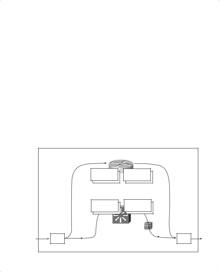
A CEF-based multilayer switch consists of two basic functional blocks, as shown in Figure 13-3: The Layer 3 Engine is involved in building routing information that the Layer 3 Forwarding Engine can use to switch packets in hardware.
Figure 13-3 Packet Flow Through a CEF-Based Multilayer Switch
|
Layer 3 Engine |
|
|
Routing Table |
ARP Table |
|
Reorder entries |
Resolve MAC |
|
addresses |
|
|
according to |
|
|
of each next hop |
|
|
longest prefix match. |
|
|
in the FIB. |
|
|
|
|
|
FIB |
Adjacency Table |
CEF Punt |
|
Rewrite |
|
Engine |
|
(to L3 Engine) |
|
|
|
Layer 3 |
|
|
|
|
|
Forwarding Engine |
|
Ingress |
|
Ingress |
Packet |
Normal CEF |
Packet |
|
|
|
|
(to L3 Fwd Engine) |
|

314 Chapter 13: Multilayer Switching
Forwarding Information Base (FIB)
The Layer 3 engine (essentially a router) maintains routing information, whether from static routes or dynamic routing protocols. Basically, the routing table is reformatted into an ordered list with the most specific route first, for each IP destination subnet in the table. The new format is called
a Forwarding Information Base (FIB) and contains routing or forwarding information that the network prefix can reference.
In other words, a route to 10.1.0.0/16 might be contained in the FIB, along with routes to 10.1.1.0/24 and 10.1.1.128/25, if those exist. Notice that these examples are increasingly more specific subnets. In the FIB, these would be ordered with the most specific, or longest match, first, followed by less specific subnets. When the switch receives a packet, it can easily examine the destination address and find the longest match entry in the FIB.
The FIB also contains the next-hop address for each entry. When a longest match entry is found in the FIB, the Layer 3 next-hop address is found, too.
You might be surprised to know that the FIB also contains host route (subnet mask 255.255.255.255) entries. These are not normally found in the routing table unless they are advertised or manually configured. Host routes are maintained in the FIB for the most efficient routing lookup to directly connected or adjacent hosts.
Like a routing table, the FIB is dynamic in nature. When the Layer 3 engine sees a change in the routing topology, it sends an update to the FIB. Any time the routing table receives a change to a route prefix or the next-hop address, the FIB receives the same change. Also, if a next-hop address is changed or aged out of the Address Resolution Protocol (ARP) table, the FIB must reflect the same change.
After the FIB is built, packets can be forwarded along the bottom dashed path in Figure 13-3. This follows the hardware switching process, where no “expensive” or time-consuming operations are needed. At times, a packet cannot be switched in hardware, according to the FIB. Packets are then marked as “CEF punt” and are immediately sent to the Layer 3 engine for further processing, as shown in the top dashed path in Figure 13-3. Some of the conditions that cause this are as follows:
■An entry cannot be located in the FIB.
■The FIB table is full.
■The IP Time To Live (TTL) has expired.
■The maximum transmission unit (MTU) is exceeded, and the packet must be fragmented.
■An Internet Control Message Protocol (ICMP) redirect is involved.
■The encapsulation type is not supported.

Multilayer Switching with CEF 315
■Tunneled packets, where a compression or encryption operation is needed.
■An access list with the log option is triggered.
■A Network Address Translation (NAT) operation must be performed (except on the Catalyst 6500 Supervisor 720, which can handle NAT in hardware).
CEF operations can be handled on a single hardware platform, as with the Catalyst 3550 switch. The FIB is generated and contained centrally in the switch. CEF can also be optimized through the use of specialized forwarding hardware, using the following techniques:
■Accelerated CEF (aCEF)—CEF is distributed across multiple Layer 3 forwarding engines, typically located on Catalyst 6500 line cards. These engines do not have the capability to store and use the entire FIB, so only a portion of the FIB is downloaded to them at any time. This functions as a FIB “cache,” containing entries that are likely to be used again. If FIB entries are not found in the cache, requests are sent to the Layer 3 engine for more FIB information. The net result is that CEF is accelerated on the line cards, but not necessarily at a sustained wirespeed rate.
■Distributed CEF (dCEF)—CEF can be completely distributed among multiple Layer 3 forwarding engines for even greater performance. Because the FIB is self-contained for complete Layer 3 forwarding, it can be replicated across any number of independent Layer 3 forwarding engines. The Catalyst 6500 has line cards that support dCEF, each with its own FIB table and forwarding engine. A central Layer 3 engine (the MSFC2, for example) maintains the routing table and generates the FIB, which is then dynamically downloaded in full to each of the line cards.
Adjacency Table
A router normally maintains a routing table containing Layer 3 network and next-hop information, and an ARP table containing Layer 3 to Layer 2 address mapping. These tables are kept independently.
Recall that the FIB keeps the Layer 3 next-hop address for each entry. To streamline packet forwarding even more, the FIB has corresponding Layer 2 information for every next-hop entry. This portion of the FIB is called the adjacency table, consisting of the MAC addresses of nodes that can be reached in a single Layer 2 hop.
The adjacency table information is built from the ARP table. As a next-hop address receives a valid ARP entry, the adjacency table is updated. If an ARP entry does not exist, the FIB entry is marked as “CEF glean.” This means that the Layer 3 forwarding engine can’t forward the packet in hardware, due to the missing Layer 2 next-hop address. The packet is sent to the Layer 3 engine so that it can generate an ARP request and receive an ARP reply. This is known as the “CEF glean” state, where the Layer 3 engine must glean the next-hop destination’s MAC address.