

BCMSN Exam Certification Guide
.pdf236Chapter 9: Traditional Spanning Tree Protocol
15.Suppose two switches are connected by a common link. Each must decide which one will have the Designated Port on the link. Which switch takes on this role, if these STP advertisements occur?
•The link is on switch A’s port number 12 and on switch B’s port number 5.
•Switch A has a Bridge ID of 32,768:0000.1111.2222, and switch B has 8192:0000.5555.6666.
•Switch A advertises a Root Path Cost of 8, while B advertises 12.
16.Using the default STP timers, how long does it take for a port to move from the Blocking state to the Forwarding state?
17.If the Root Bridge sets the Topology Change flag in the BPDU, what must the other switches in the network do?
18.Over what VLAN(s) does the CST form of STP run?
a.VLAN 1
b.All active VLANs
c.All VLANs (active or inactive)
d.The native VLAN
19.What is the major difference between PVST and PVST+?
20.Two switches are connected by a common active link. When might neither switch have a Designated Port on the link?
a.When neither has a better Root Path Cost.
b.When the switches are actually the primary and secondary Root Bridges.
c.When one switch has its port in the Blocking state.
d.Never; this can’t happen.

This chapter covers the following topics that you need to master for the CCNP BCMSN exam:
■STP Root Bridge—This section discusses the importance of identifying a Root Bridge, as well as suggestions for its placement in the network. This section also presents the Root Bridge configuration commands.
■Spanning Tree Customization—This section covers the configuration commands that allow you to alter the spanning tree’s topology.
■Tuning Spanning Tree Convergence—This section discusses how to alter, or tune, the STP timers to achieve optimum convergence times in a network.
■Redundant Link Convergence—This section describes the methods that cause a network to converge more quickly after a topology change.
■Troubleshooting STP—This section offers a brief summary of the commands you can use to verify that an STP instance is working properly.

C H A P T E R 10
Spannning Tree Configuration
This chapter presents the design and configuration considerations necessary to implement the IEEE 802.1D Spanning Tree Protocol (STP) in a campus network. This chapter also provides a refresher on the commands needed to configure the STP features, as previously described in Chapter 9, “Traditional Spanning Tree Protocol.”
You can also tune STP or make it converge more efficiently in a given network. This chapter presents the theory and commands needed to accomplish this.
“Do I Know This Already?” Quiz
The purpose of the “Do I Know This Already?” quiz is to help you decide what parts of this chapter to use. If you already intend to read the entire chapter, you do not necessarily need to answer these questions now.
The quiz, derived from the major sections in the “Foundation Topics” portion of the chapter, helps you determine how to spend your limited study time.
Table 10-1 outlines the major topics discussed in this chapter and the “Do I Know This Already?” quiz questions that correspond to those topics.
Table 10-1 “Do I Know This Already?” Foundation Topics Section-to-Question Mapping
Foundation Topics Section |
Questions Covered in This Section |
|
|
STP Root Bridge |
1–5 |
|
|
Spanning Tree Customization |
6–7 |
|
|
Tuning Spanning Tree Convergence |
8–9 |
|
|
Redundant Link Convergence |
10–12 |
|
|
|
|
CAUTION The goal of self-assessment is to gauge your mastery of the topics in this chapter. If you do not know the answer to a question or are only partially sure of the answer, you should mark this question wrong. Giving yourself credit for an answer you correctly guess skews your self-assessment results and might give you a false sense of security.

240Chapter 10: Spannning Tree Configuration
1.Where should the Root Bridge be placed on a network?
a.On the fastest switch
b.Closest to the most users
c.Closest to the center of the network
d.On the least-used switch
2.Which of the following is a result of a poorly placed Root Bridge in a network?
a.Bridging loops form.
b.STP topology can’t be resolved.
c.STP topology can take unexpected paths.
d.Root Bridge election flapping.
3.Which of these parameters should you change to make a switch become a Root Bridge?
a.Switch MAC address
b.Path Cost
c.Port Priority
d.Bridge Priority
4.What is the default STP Bridge Priority on a Catalyst switch?
a.0
b.1
c.32,768
d.65,535
5.Which of the following commands can make a switch become the Root Bridge for VLAN 5, assuming that all switches have the default STP parameters?
a.spanning-tree root
b.spanning-tree root vlan 5
c.spanning-tree vlan 5 priority 100
d.spanning-tree vlan 5 root

“Do I Know This Already?” Quiz 241
6.What is the default Path Cost of a Gigabit Ethernet switch port?
a.1
b.2
c.4
d.19
e.1000
7.What command can change the Path Cost of interface Gigabit Ethernet 3/1 to a value of 8?
a.spanning-tree path-cost 8
b.spanning-tree cost 8
c.spanning-tree port-cost 8
d.spanning-tree gig 3/1 cost 8
8.What happens if the Root Bridge switch and another switch are configured with different STP hello timer values?
a.Nothing; each sends hellos at different times.
b.A bridging loop could form because the two switches are out of sync.
c.The switch with the lower hello timer becomes the Root Bridge.
d.The other switch changes its hello timer to match the Root Bridge.
9.What network diameter value is the basis for the default STP timer calculations?
a.1
b.3
c.7
d.9
e.15
10.Where should the STP PortFast feature be used?
a.An access layer switch port connected to a PC
b.An access layer switch port connected to a hub
c.A distribution layer switch port connected to an access layer switch
d.A core layer switch port

242Chapter 10: Spannning Tree Configuration
11.Where should the STP UplinkFast feature be enabled?
a.An access layer switch
b.A distribution layer switch
c.A core layer switch
d.All of the above
12.If used, the STP BackboneFast feature should be enabled on which of these?
a.All backbone or core layer switches
b.All backbone and distribution layer switches
c.All access layer switches
d.All switches in the network
The answers to the “Do I Know This Already?” quiz are found in Appendix A, “Answers to Chapter ‘Do I Know This Already?’ Quizzes and Q&A Sections.” The suggested choices for your next step are as follows:
■10 or less overall score—Read the entire chapter. This includes the “Foundation Topics,” “Foundation Summary,” and “Q&A” sections.
■11 or 12 overall score—If you want more review on these topics, skip to the “Foundation Summary” section and then go to the “Q&A” section at the end of the chapter. Otherwise, move to Chapter 11, “Protecting the Spanning Tree Protocol Topology.”

STP Root Bridge 243
Foundation Topics
STP Root Bridge
STP and its computations are predictable; however, other factors exist that might subtly influence STP decisions, making the resulting tree structure neither expected nor ideal.
The network administrator can make adjustments to the Spanning Tree operation to control its behavior. The location of the Root Bridge should be determined as part of the design process. You can also use redundant links for load balancing in parallel, if configured correctly. You can also configure Spanning Tree Protocol (STP) to converge quickly and predictably in the event of a major topology change.
NOTE By default, STP is enabled on all ports of a switch. STP should remain enabled in a network to prevent bridging loops from forming. However, if STP has been disabled, you can re-enabled it with the following global configuration command:
Switch (config)# spanning-tree vlan vlan-id
Root Bridge Placement
While STP is wonderfully automatic with its default values and election processes, the resulting tree structure might perform quite differently than expected. The Root Bridge election is based on the idea that one switch is chosen as a common reference point, and all other switches choose ports that have the best cost path to the Root. The Root Bridge election is also based on the idea that the Root Bridge can become a central hub that interconnects other legs of the network. Therefore, the Root Bridge can be faced with heavy switching loads in its central location.
If the Root Bridge election is left to its default state, several things can occur to make a poor choice. For example, the slowest switch (or bridge) can be elected as the Root Bridge. If heavy traffic loads are expected to pass through the Root Bridge, the slowest switch is not the ideal candidate. Recall that the only criteria for Root Bridge election is the lowest Bridge ID (Bridge Priority and MAC address)—not necessarily the best choice to ensure optimal performance. If the slowest switch has the same Bridge Priority as the others and has the lowest MAC address, the slowest switch will be chosen as the Root.
A second factor to consider relates to redundancy. If all switches are left to their default states, only one Root Bridge is elected with no clear choice for a “backup.” What happens if that switch fails? Another Root Bridge election occurs, but again, the choice might not be the ideal switch or the ideal location.
244 Chapter 10: Spannning Tree Configuration
The final consideration is the location of the Root Bridge switch. As before, an election with default switch values could place the Root Bridge in an unexpected location in the network. More importantly, an inefficient Spanning Tree structure could result, causing traffic from a large portion of the network to take a long and winding path just to pass through the Root Bridge.
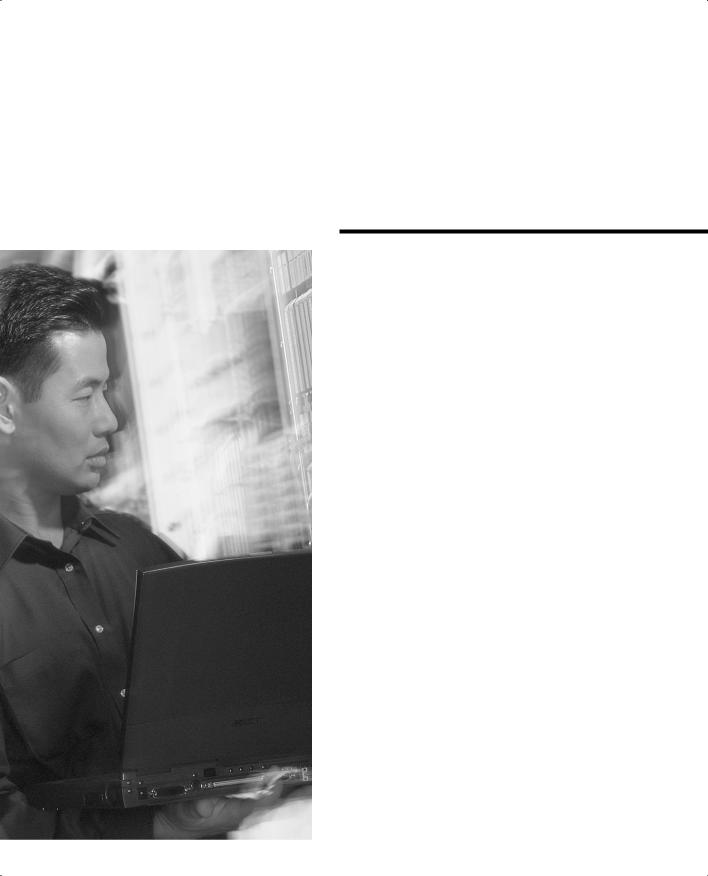
Figure 10-1 shows a portion of a real-world hierarchical campus network.
Figure 10-1 Campus Network with an Inefficient Root Bridge Election
Catalyst A |
|
|
|
|
|
|
Catalyst B |
|
32768 |
|
|
|
|
|
32768 |
||
00-00-00-00-00-0a |
|
|
|
|
|
|
|
00-00-00-00-00-0b |
|
|
|
|
|
|
|||
100Mbps |
|
100Mbps |
|
|
1Gbps |
|||
Cost = 19 |
|
Cost = 19 |
|
|
Cost = 4 |
|||
Catalyst C |
|
|
|
|
|
|
Catalyst D |
|
32768 |
|
|
|
1Gbps |
|
32768 |
||
|
|
|
|
|||||
00-00-00-00-00-0c |
|
|
|
|
|
00-00-00-00-00-0d |
||
|
|
|
|
|||||
|
|
|
|
Cost = 4 |
|
|
|
|
|
|
1Gbps |
1Gbps |
|||||
|
|
Cost = 4 |
Cost = 4 |
|||||
|
|
|
|
|
|
|
|
|
|
|
|
|
|
|
|
|
|
Catalyst E 32768
00-00-00-00-00-0e
Access Layer
Core Layer
Server Farm
Catalyst switches A and B are two access layer devices; Catalysts C and D form the core layer and Catalyst E connects a server farm into the network core. Notice that most of the switches use redundant links to other layers of the hierarchy, as suggested in Chapter 2, “Modular Network Design.” At the time of this example, however, many switches like Catalyst B still have only a single connection into the core. These switches are slated for an “upgrade,” where a redundant link will be added to the other half of the core.
As you will see, Catalyst A will become the Root Bridge because of its low MAC address. All switches have been left to their default STP states—the Bridge Priority of each is 32,768.
STP Root Bridge 245
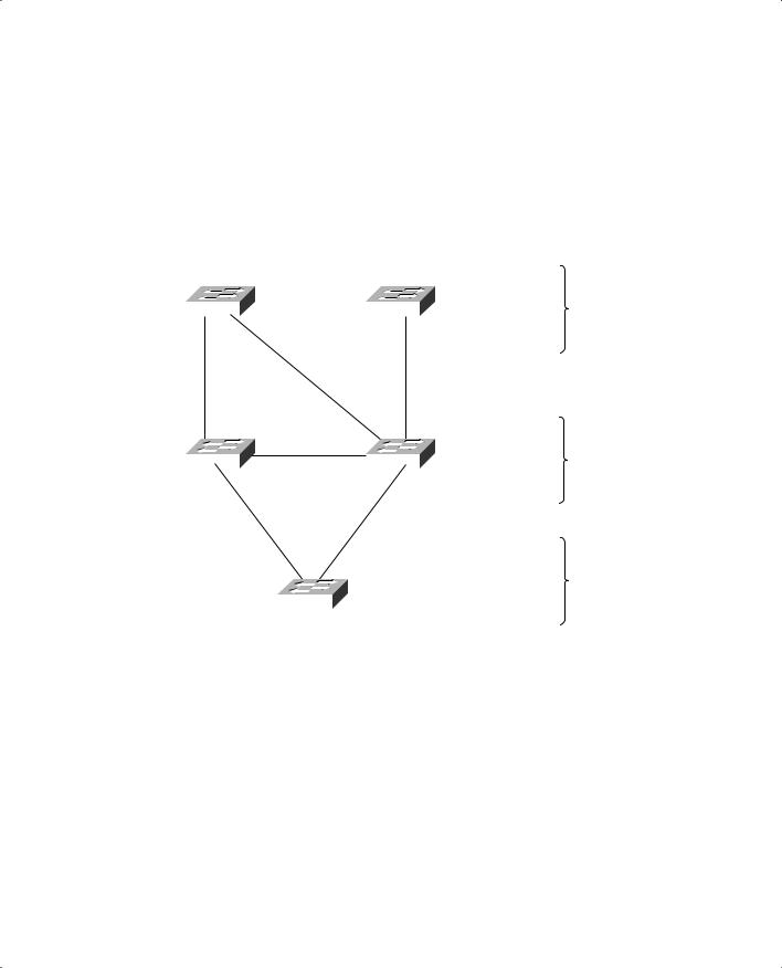
Figure 10-2 shows the converged state of STP. For the purposes of this discussion, the Root Ports and Designated Ports are simply shown on the network diagram. As an exercise, you should work out the Spanning Tree based on the information shown in the figure. The more examples you can work out by hand, the better you will understand the entire Spanning Tree process.
Figure 10-2 Campus Network with STP Converged
Root Bridge
Catalyst A |
|
|
|
|
|
|
|
|
|
|
|
|
|
|
|
|
Catalyst B |
|
||||
|
|
|
|
|
|
|
|
|||||||||||||||
32768 |
|
|
|
|
|
|
|
|
|
|
|
|
|
|
|
32768 |
|
|||||
00-00-00-00-00-0a |
|
|
|
|
|
|
|
|
DP |
|
|
|
|
|
00-00-00-00-00-0b |
Access Layer |
||||||
|
|
|
|
|
|
|
|
|
|
|
||||||||||||
DP |
|
|
|
|
|
|
|
|
|
|
|
|
|
RP |
|
|||||||
|
|
|
|
|
|
|
|
|
|
|
|
|
|
|||||||||
|
|
|
|
|
|
|
|
19 |
|
|
|
|
|
|
|
|
|
|||||
|
|
|
|
|
|
|
|
|
|
|
|
|
|
|
|
|||||||
19 |
|
|
|
|
|
|
|
|
|
4 |
|
|||||||||||
|
|
|
|
|
|
|
|
|
|
|
|
|
|
|
|
RP |
|
|||||
|
|
|
|
|
|
|
|
|
|
|
|
|
|
|
|
|
||||||
RP |
|
|
|
|
|
|
|
|
|
|
|
|
|
|
|
|
|
|
DP |
|
||
|
|
|
|
|
|
|
|
|
|
|
|
|
|
|
|
|
|
|
||||
|
|
|
|
|
|
|
|
|
|
|
|
|
|
|
|
|
||||||
Catalyst C |
|
|
|
|
X |
|
|
|
|
|
Catalyst D |
|
||||||||||
32768 |
|
|
|
|
|
|
|
|
|
|
|
|
|
|
|
|
|
|
|
Core Layer |
||
|
|
|
|
|
|
|
|
|
|
|
|
|
|
|
||||||||
|
|
|
|
|
|
|
|
|
|
|
|
|
|
|
|
|
|
|
||||
00-00-00-00-00-0c |
|
|
DP |
|
|
|
|
DP 4 |
|
|
|
|
|
00-00-00-00-00-0d |
|
|||||||
|
|
|
|
|
|
|
|
|
|
|
|
|
|
DP |
|
|||||||
4 |
|
|
|
|
|
|
4 |
|
|
|
||||||||||||
|
|
|
|
|
|
|
|
|
|
|
|
|||||||||||
|
|
|
|
|
|
|
|
|
RP |
|
|
|
X |
|
|
|
|
|
|
|
||
|
|
|
|
|
|
|
|
|
|
|
|
|
|
|
|
|
|
|
|
|
|
Server Farm |
|
|
|
|
|
|
|
|
|
|
|
|
|
|
|
|
|
|
|
|
|
|
|
|
|
|
|
|
|
|
|
|
|
|
|
|
|
|
|
|
|
|
|
|
|
|
|
|
|
|
|
|
|
|
|
|
|
|
Catalyst E |
|
|
|
|
|
|
|
|||
|
|
|
|
|
|
|
|
|
|
32768 |
|
|
|
|
|
|
|
|
|
|
||
|
|
|
|
|
|
|
|
|
|
00-00-00-00-00-0e |
|
|
|
|
|
|
|
|||||
Notice that Catalyst A, one of the access layer switches, has been elected the Root Bridge. Unfortunately, Catalyst A cannot take advantage of the 1-Gbps links, unlike the other switches. Also note the location of the X symbols over the ports that are neither Root Ports nor Designated Ports. These ports will enter the Blocking state.
Finally, Figure 10-3 shows the same network with the Blocking links removed. Now, you can see the true structure of the final Spanning Tree.