

BCMSN Exam Certification Guide
.pdf176 Chapter 7: VLAN Trunking Protocol (VTP)
Configuring the VTP Mode
Next, you need to choose the VTP mode for the new switch. The three VTP modes of operation and their guidelines for use are as follows:
■Server mode—Server mode can be used on any switch in a management domain, even if other server and client switches are in use. This mode provides some redundancy in the event of a server failure in the domain. However, each VTP management domain should have at least one server. The first server defined in a network also defines the management domain that will be used by future VTP servers and clients. Server mode is the default VTP mode and allows VLANs to be created and deleted.
NOTE Multiple VTP servers can coexist in a domain. This is usually recommended for redundancy. The servers do not elect a primary or secondary server—they all simply function as servers. If one server is configured with a new VLAN or VTP parameter, it advertises the changes to the rest of the domain. All other servers synchronize their VTP databases to this advertisement, just as any VTP client would.
■Client mode—If other switches are in the management domain, a new switch should be configured for client mode operation. In this way, the switch learns any existing VTP information from a server.
If this switch is used as a redundant server, it should start out in client mode to learn all VTP information from reliable sources. If the switch was initially configured for server mode instead, it might propagate incorrect information to the other domain switches. After the switch has learned the current VTP information, it can be reconfigured for server mode.
■Transparent mode—This mode is used if a switch is not going to share VLAN information with any other switch in the network. VLANs can still be created, deleted, and modified on the transparent switch. However, they are not advertised to other neighboring switches. VTP advertisements received by a transparent switch, however, are forwarded to other switches on trunk links.
Keeping switches in transparent mode can eliminate the chance for duplicate, overlapping VLANs in a large network with many network administrators. For example, two administrators might configure VLANs on switches in their respective areas but use the same VLAN identification or VLAN number. Even though the two VLANs have different meanings and purposes, they could overlap if both administrators advertised them using VTP servers.
You can configure the VTP mode with the following sequence of global configuration commands:
Switch(config)# vtp mode {server | client | transparent}
Switch(config)# vtp password password

VTP Configuration 177
If the domain is operating in secure mode, a password can also be defined. The password can be configured only on VTP servers and clients. It builds an MD5 digest that is sent in VTP
advertisements (servers) and validates received advertisements (clients). The password is a string of 1 to 32 characters (case-sensitive).
If secure VTP is implemented using passwords, begin by configuring a password on the VTP servers. The client switches retain the last known VTP information but are unable to process received advertisements until the same password is configured on them, too.
Configuring the VTP Version
Two versions of VTP are available for use in a management domain. Catalyst switches are capable of running either VTP version 1 or VTP version 2. Within a management domain, the two versions are not interoperable. Therefore, the same VTP version must be configured on every switch in a domain. VTP version 1 is the default protocol on a switch.
If a switch is capable of running VTP version 2, however, a switch can coexist with other version 1 switches, as long as its VTP version 2 is not enabled. This situation becomes important if you want to use version 2 in a domain. Then, only one server mode switch needs to have VTP version 2 enabled. The new version number is propagated to all other version 2-capable switches in the domain, causing them all to automatically enable version 2 for use.
The two versions of VTP differ in the features they support. VTP version 2 offers the following additional features over version 1:
■Version-dependent transparent mode—In transparent mode, VTP version 1 matches the VTP version and domain name before forwarding the information to other switches using VTP. VTP version 2 in transparent mode forwards the VTP messages without checking the version number. Because only one domain is supported in a switch, the domain name doesn’t have to be checked.
■Consistency checks—VTP version 2 performs consistency checks on the VTP and VLAN parameters entered from the command line interface (CLI) or by Simple Network Management Protocol (SNMP). This checking helps prevent errors in such things as VLAN names and numbers from being propagated to other switches in the domain. However, no consistency checks are performed on VTP messages that are received on trunk links or on configuration and database data that is read from NVRAM.
■Token Ring support—VTP version 2 supports the use of Token Ring switching and Token Ring VLANs. (If Token Ring switching is being used, VTP version 2 must be enabled.)

178 Chapter 7: VLAN Trunking Protocol (VTP)
■Unrecognized Type-Length-Value (TLV) support—VTP version 2 switches propagate received configuration change messages out other trunk links, even if the switch supervisor cannot parse or understand the message. For example, a VTP advertisement contains a Type field to denote what type of VTP message is being sent. VTP message type 1 is a summary advertisement, and message type 2 is a subset advertisement. An extension to VTP that utilizes other message types and other message length values could be in use. Instead of dropping the unrecognized VTP message, version 2 still propagates the information and keeps a copy in NVRAM.
The VTP version number is configured using the following global configuration command:
Switch(config)# vtp version {1 | 2}
By default, a switch uses VTP version 1.
VTP Status
The current VTP parameters for a management domain can be displayed using the show vtp status command. Example 7-1 demonstrates some sample output of this command.
Example 7-1 show vtp status Reveals VTP Parameters for a Management Domain
Switch# show vtp status |
|
VTP Version |
: 2 |
Configuration Revision |
: 89 |
Maximum VLANs supported locally : 1005 |
|
Number of existing VLANs |
: 74 |
VTP Operating Mode |
: Client |
VTP Domain Name |
: CampusDomain |
VTP Pruning Mode |
: Enabled |
VTP V2 Mode |
: Disabled |
VTP Traps Generation |
: Disabled |
MD5 digest |
: 0x4B 0x07 0x75 0xEC 0xB1 0x3D 0x6F 0x1F |
Configuration last modified by 192.168.199.1 at 11-19-02 09:29:56
Switch#
VTP message and error counters can also be displayed with the show vtp counters command. You can use this command for basic VTP troubleshooting to see if the switch is interacting with other VTP nodes in the domain. Example 7-2 demonstrates some sample output from the show vtp counters command.

VTP Pruning 179
Example 7-2 show vtp counters Reveals VTP Message and Error Counters
Switch# show vtp counters |
|
|
|
VTP statistics: |
|
|
|
Summary advertisements received |
: 1 |
|
|
Subset advertisements received |
: 2 |
|
|
Request advertisements received |
: 1 |
|
|
Summary advertisements transmitted |
: 1630 |
|
|
Subset advertisements transmitted |
: 0 |
|
|
Request advertisements transmitted |
: 4 |
|
|
Number of config revision errors |
: 0 |
|
|
Number of config digest errors |
: 0 |
|
|
Number of V1 summary errors |
: 0 |
|
|
VTP pruning statistics: |
|
|
|
Trunk |
Join Transmitted Join Received |
Summary advts received from |
|
|
|
|
non-pruning-capable device |
---------------- ---------------- ---------------- ---------------------------
Gi0/1 |
82352 |
82931 |
0 |
Switch# |
|
|
|
VTP Pruning
Recall that by definition, a switch must forward broadcast frames out all available ports in the broadcast domain because broadcasts are destined everywhere there is a listener. Multicast frames, unless forwarded by more intelligent means, follow the same pattern.
In addition, frames destined for an address that the switch has not yet learned or has forgotten (the MAC address has aged out of the address table) must be forwarded out all ports in an attempt to find the destination. These frames are referred to as unknown unicast.
When forwarding frames out all ports in a broadcast domain or VLAN, trunk ports are included if they transport that VLAN. By default, a trunk link transports traffic from all VLANs, unless specific VLANs are removed from the trunk. Generally, in a network with several switches, trunk links are enabled between switches, and VTP is used to manage the propagation of VLAN information. This scenario causes the trunk links between switches to carry traffic from all VLANs—not just from the specific VLANs created.
180 Chapter 7: VLAN Trunking Protocol (VTP)
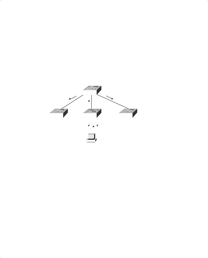
Consider the network shown in Figure 7-4. When end user HostPC in VLAN 3 sends a broadcast, Catalyst switch C forwards the frame out all VLAN 3 ports, including the trunk link to Catalyst A. Catalyst A, in turn, forwards the broadcast on to Catalysts B and D over those trunk links. Catalysts B and D forward the broadcast out only their access links that have been configured for VLAN 3. If Catalysts B and D do not have any active users in VLAN 3, forwarding that broadcast frame to them would consume bandwidth on the trunk links and processor resources in both switches, only to have switches B and D discard the frames.
Figure 7-4 Flooding in a Catalyst Switch Network
Catalyst A (VLANs 1-1000)
Catalyst B |
|
|
|
|
Catalyst D |
||
|
|
Catalyst C |
|||||
|
|
||||||
|
|
|
|
|
|
|
|
|
|
|
|
|
|
|
|
|
|
|
|
|
|
|
|
|
|
|
|
|
|
|
|
|
|
|
|
|
|
|
|
|
|
|
|
|
|
VLAN 2 |
|
|
|
|
|
VLANs 3,4 |
||||||||
|
|
|
|
|
||||||||||
|
|
|
|
|
|
|
|
|
|
|
|
|
|
|
|
|
|
|
|
|
|
|
|
|
|
|
|
|
|
|
|
|
|
|
|
|
|
|
|
|
|
|
|
|
|
|
|
|
|
|
|
|
|
|
|
|
|
|
|
|
|
|
|
|
|
|
|
|
|
|
|
|
|
|
Host PC
VLAN 3
VTP pruning makes more efficient use of trunk bandwidth by reducing unnecessary flooded traffic. Broadcast and unknown unicast frames on a VLAN are forwarded over a trunk link only if the switch on the receiving end of the trunk has ports in that VLAN. VTP pruning occurs as an extension to VTP version 1, using an additional VTP message type. When a Catalyst switch has a port associated with a VLAN, the switch sends an advertisement to its neighbor switches that it has active ports on that VLAN. The neighbors keep this information, enabling them to decide if flooded traffic from a VLAN should use a trunk port or not.
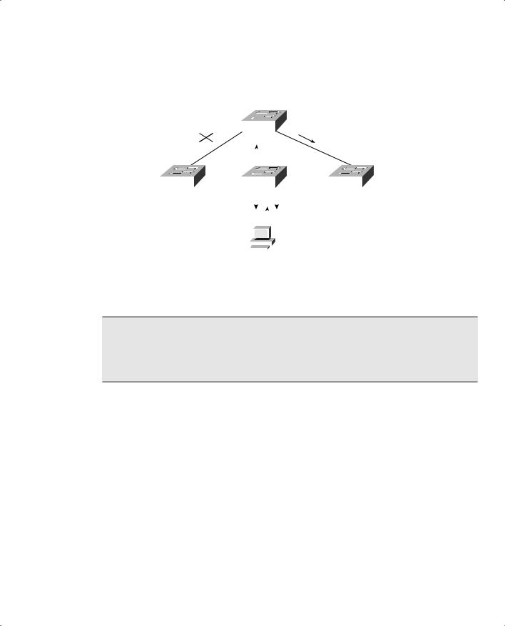
Figure 7-5 shows the network from Figure 7-4 with VTP pruning enabled. Because Catalyst B has not advertised its use of VLAN 3, Catalyst A will prune VLAN 3 from the trunk to B and will choose not to flood VLAN 3 traffic to B over the trunk link. Catalyst D has advertised the need for VLAN 3, so traffic will be flooded to it.
VTP Pruning 181
Figure 7-5 Flooding in a Catalyst Switch Network Using VTP Pruning
Catalyst A (VLANs 1-1000)
|
|
|
|
|
|
|
|
|
Catalyst B |
|
Catalyst C |
Catalyst D |
|||||
|
||||||||
|
|
|
|
|
|
|
|
|
|
|
|
|
|
|
|
|
|
|
|
|
|
|
|
|
|
|
|
|
|
|
|
|
|
|
|
|
|
|
|
|
|
|
|
|
|
|
|
|
|
|
|
|
|
|
|
|
VLAN 2 |
|
|
|
|
|
VLANs 3,4 |
||||||||
|
|
|
|
|
||||||||||
|
|
|
|
|
|
|
|
|
|
|
|
|
|
|
|
|
|
|
|
|
|
|
|
|
|
|
|
|
|
|
|
|
|
|
|
|
|
|
|
|
|
|
|
|
|
|
|
|
|
|
|
|
|
|
|
|
|
|
|
|
|
|
|
|
|
|
|
|
|
|
|
|
|
|
Host PC
VLAN 3
NOTE Even when VTP pruning has determined that a VLAN is not needed on a trunk, an instance of the Spanning Tree Protocol (STP) will run for every VLAN that is allowed on the trunk link. To reduce the number of STP instances, you should manually “prune” unneeded VLANs from the trunk and allow only the needed ones. Use the switchport trunk allowed vlan command to identify the VLANs that should be added or removed from a trunk.
Enabling VTP Pruning
By default, VTP pruning is disabled on IOS-based switches. To enable pruning, use the following global configuration command:
Switch(config)# vtp pruning
If this command is used on a VTP server, pruning is enabled for the entire management domain. When pruning is enabled, all general-purpose VLANs become eligible for pruning on all trunk links, if needed. However, you can modify the default list of pruning eligibility with the following interface configuration command:
Switch(config)# interface type mod/num
Switch(config-if)# switchport trunk pruning vlan {add | except | none | remove} vlan-list

182 Chapter 7: VLAN Trunking Protocol (VTP)
By default, VLANs 2 through 1001 are eligible, or “enabled,” for potential pruning on every trunk. Use the following keywords with the command to tailor the list:
■vlan-list—An explicit list of eligible VLAN numbers (anything from 2 to 1001), separated by commas or by dashes.
■all—All active VLANs (1 to 4094) are eligible.
■add vlan-list—A list of VLAN numbers (anything from 2 to 1001) are added to the already configured list; this is a shortcut to keep from typing out a long list of numbers.
■except vlan-list—All VLANs (1 to 4094) are eligible except for the VLAN numbers listed (anything from 2 to 1001); this is a shortcut to keep from typing out a long list of numbers.
■remove vlan-list—A list of VLAN numbers (anything from 2 to 1001) are removed from the already configured list; this is a shortcut to keep from typing out a long list of numbers.
NOTE Be aware that VTP pruning has no effect on switches in the VTP transparent mode. Instead, those switches must be configured manually to “prune” VLANs from trunk links. In this case, pruning is always configured on the upstream side of a trunk.
By default, VLANs 2 to 1001 are eligible for pruning. VLAN 1 has a special meaning because it is normally used for control traffic and is never eligible for pruning. In addition, VLANs 1002 through 1005 are reserved for Token Ring and FDDI VLANs and are never eligible for pruning.
Troubleshooting VTP
If a switch does not seem to be receiving updated information from a VTP server, consider these possible causes:
■The switch is configured for VTP transparent mode. In this mode, incoming VTP advertisements are not processed; they are relayed only to other switches in the domain.
■If the switch is configured as a VTP client, there might not be another switch functioning as a VTP server. In this case, configure the local switch to become a VTP server itself.
■The link toward the VTP server is not in trunking mode. VTP advertisements are sent only over trunks. Use the show interface type mod/num switchport to verify the operational mode as a trunk.
■Make sure the VTP domain name is correctly configured to match that of the VTP server.
■Make sure the VTP version is compatible with other switches in the VTP domain.

Troubleshooting VTP 183
■Make sure the VTP password matches others in the VTP domain. If the server doesn’t use a password, make sure the password is disabled or cleared on the local switch.
NOTE Above all else, verify a switch’s VTP configuration BEFORE connecting it to a production network. If the switch has been previously configured or used elsewhere, it might already be in VTP server mode with a VTP configuration revision number that is higher than other switches in the production VTP domain. In that case, other switches will listen and learn from the new switch because it has a higher revision number and must know more recent information. This could cause the new switch to introduce bogus VLANs into the domain or, worse yet, to cause all other switches in the domain to delete all their active VLANs.
To prevent this from happening, reset the configuration revision number of every new switch that is added to a production network.
Table 7-2 lists and describes the commands that are useful for verifying or troubleshooting VTP configuration.
Table 7-2 VTP Configuration Troubleshooting Commands
Function |
Command syntax |
|
|
Display current VTP parameters, including the |
show vtp status |
last advertising server |
|
|
|
Display VTP advertisement and pruning statistics |
show vtp counters |
|
|
Display defined VLANs |
show vlan brief |
|
|
Display trunk status, including pruning eligibility |
show interface type mod/num switchport |
|
|
Display VTP pruning state |
show interface type mod/num pruning |
|
|

184 Chapter 7: VLAN Trunking Protocol (VTP)
Foundation Summary
The Foundation Summary is a collection of information that provides a convenient review of many key concepts in this chapter. If you are already comfortable with the topics in this chapter, this summary can help you recall a few details. If you just read this chapter, this review should help solidify some key facts. If you are doing your final preparation before the exam, this information is a convenient way to review the day before the exam.
Table 7-3 Catalyst VTP Modes
VTP Mode |
Characteristics |
|
|
Server |
All VLAN and VTP configuration changes occur here. The server advertises settings and |
|
changes to all other servers and clients in a VTP domain. (This is the default mode for |
|
Catalyst switches.) |
|
|
Client |
Listens to all VTP advertisements from servers in a VTP domain. Advertisements are |
|
relayed out other trunk links. No VLAN or VTP configuration changes can be made on a |
|
client. |
|
|
Transparent |
VLAN configuration changes are made locally, independent of any VTP domain. VTP |
|
advertisements are not received but merely relayed out other trunk links, if possible. |
|
|
Table 7-4 Types of VTP Advertisements
Advertisement Type |
Function |
|
|
Summary |
Sent by server every 300 seconds and after a topology change. Contains a |
|
complete dump of all VTP domain information. |
|
|
Subset |
Sent by server only after a VLAN configuration change. Contains only |
|
information about the specific VLAN change. |
|
|
Advertisement request |
Sent by client when additional VTP information is needed. Servers sent |
|
summary or subset advertisements in response. |
|
|
Pruning request |
Sent by clients and servers to announce VLANs that are in active use on |
|
local switch ports. (These messages are destined for nearest-neighbor |
|
switches and are not relayed throughout the domain.) |
|
|

Foundation Summary 185
Table 7-5 VTP Configuration Commands
Task |
Command Syntax |
|
|
Define the VTP domain |
vtp domain domain-name |
|
|
Set the VTP mode |
vtp mode {server | client | transparent} |
|
|
Define an optional VTP |
vtp password password |
password |
|
|
|
Configure VTP version |
vtp version {1 | 2} |
|
|
Enable VTP pruning |
vtp pruning |
|
|
Select VLANs eligible for |
interface type mod/num |
pruning on a trunk interface |
switchport trunk pruning vlan {add | except | none | remove} vlan-list |
|
|