- •Table of Contents
- •Cisco Switching Black Book
- •Introduction
- •Overview
- •Is This Book for You?
- •How to Use This Book
- •The Black Book Philosophy
- •Chapter 1: Network Switching Fundamentals
- •In Depth
- •Physical Media and Switching Types
- •A Bit of History
- •Networking Architectures
- •The Pieces of Technology
- •Repeaters
- •Hubs
- •Bridges
- •Routers
- •Switches
- •Network Design
- •Collision Domains
- •Broadcast Domains
- •Why Upgrade to Switches?
- •Switched Forwarding
- •Switched Network Bottlenecks
- •The Rule of the Network Road
- •Switched Ethernet Innovations
- •Fast Ethernet
- •Gigabit Ethernet
- •The Cisco IOS
- •Connecting to the Switch
- •Powering Up the Switch
- •The Challenges
- •Entering and Exiting Privileged EXEC Mode
- •Entering and Exiting Global Configuration Mode
- •Entering and Exiting Interface Configuration Mode
- •Entering and Exiting Subinterface Configuration Mode
- •Saving Configuration Changes
- •Chapter 2: Basic Switch Configuration
- •In Depth
- •Campus Hierarchical Switching Model
- •Access Layer
- •Distribution Layer
- •Core Layer
- •Remote Network Monitoring
- •Connecting to the Console Port
- •Console Cable Pinouts
- •Console Connectors
- •Switch IOSs
- •The IOS Configuration Modes
- •Limiting Telnet Access
- •Implementing Privilege Levels
- •Setting the Login Passwords
- •Setting Privilege Levels
- •Assigning Allowable Commands
- •Configuring the Hostname
- •Configuring the Date and Time
- •Configuring an IP Address and Netmask
- •Configuring a Default Route and Gateway
- •Configuring Port Speed and Duplex
- •Enabling SNMP Contact
- •Logging On to a Switch
- •Setting the Login and Enable Passwords
- •Changing the Console Prompt
- •Entering a Contact Name and Location Information
- •Configuring System and Time Information
- •Configuring an IP Address and Netmask
- •Configuring a Default Route and Gateway
- •Viewing the Default Routes
- •Configuring Port Speed and Duplex
- •Enabling SNMP
- •Configuring Trap Message Targets
- •Configuring the Console Port
- •Configuring Telnet
- •Configuring the Password
- •Configuring an IP Address and Default Gateway
- •Configuring SNMP
- •Configuring ROM
- •Entering ROM Configuration Mode
- •Booting ROM Mode from a Flash Device
- •Configuring SNMP
- •Configuring RMON
- •Using Set/Clear Command Set Recall Key Sequences
- •Chapter 3: WAN Switching
- •In Depth
- •WAN Transmission Media
- •Synchronous Transport Signal (STS)
- •Cisco WAN Switches
- •MGX 8200 Series
- •IGX 8400 Series
- •WAN Switch Hardware Overview
- •Cisco WAN Switch Network Topologies
- •Network Management
- •WAN Manager
- •Accessing and Setting Up IGX and BPX Switches
- •Adding New Users
- •Using the History Command
- •Displaying a Summary of All Card Modules
- •Displaying Detailed Information for a Card Module
- •Displaying the Power and Temperature of a Switch
- •Displaying the ASM Statistics for BPX
- •Configuring the ASM Setting for BPX
- •Logging Out
- •Resetting the Switch
- •Displaying Other Switches
- •Setting the Switch Name
- •Setting the Time Zone
- •Configuring the Time and Date
- •Configuring the Control and Auxiliary Ports
- •Modifying the Functions of the Control and Auxiliary Ports
- •Configuring the Printing Function
- •Configuring the LAN Interface
- •Accessing the MGX 8850 and 8220
- •Adding New Users
- •Changing Passwords
- •Assigning a Switch Hostname
- •Displaying a Summary of All Modules
- •Displaying Detailed Information for the Current Card
- •Changing the Time and Date
- •Displaying the Configuration of the Maintenance and Control Ports
- •Displaying the IP Address
- •Configuring the IP Interface
- •Displaying the Alarm Level of the Switch
- •Chapter 4: LAN Switch Architectures
- •In Depth
- •The Catalyst Crescendo Architecture
- •ASICs
- •The Crescendo Processors
- •Crescendo Logic Units
- •Other Cisco Switch Processors, Buses, ASICs, and Logic Units
- •AXIS Bus
- •CEF ASIC
- •Phoenix ASIC
- •SAGE ASIC
- •QTP ASIC
- •QMAC
- •Bridging Types
- •Source Route Bridging
- •Source Route Transparent Bridging
- •Source Route Translational Bridging
- •Transparent Bridging
- •Source Route Switching
- •Switching Paths
- •Process Switching
- •Fast Switching
- •Autonomous Switching
- •Silicon Switching
- •Optimum Switching
- •Distributed Switching
- •NetFlow Switching
- •System Message Logging
- •Loading an Image on the Supervisor Engine III
- •Booting the Supervisor Engine III from Flash
- •Setting the Boot Configuration Register
- •Configuring Cisco Express Forwarding
- •Enabling CEF
- •Disabling CEF
- •Enabling dCEF
- •Disabling dCEF
- •Disabling CEF on an Individual Interface
- •Configuring CEF Load Balancing
- •Disabling CEF Load Balancing
- •Enabling Network Accounting for CEF
- •Setting Network Accounting for CEF to Collect Packet Numbers
- •Viewing Network Accounting for CEF Statistics
- •Viewing the Adjacency Table on the 8500 GSR
- •Clearing the Adjacency Table on the 8500 GSR
- •Clearing the Server Logging Table
- •Disabling Server Logging
- •Displaying the Logging Configuration
- •Displaying System Logging Messages
- •Chapter 5: Virtual Local Area Networks
- •In Depth
- •The Flat Network of Yesterday
- •Why Use VLANs?
- •VLAN Basics
- •A Properly Switched Network
- •Switched Internetwork Security
- •Scaling with VLANs
- •VLAN Boundaries
- •VLAN Membership Types
- •Traffic Patterns Flowing through the Network
- •VLAN Trunking
- •Trunk Types
- •LAN Emulation (LANE)
- •VLAN Trunking Protocol (VTP)
- •VTP Versions
- •VTP Advertisements
- •VTP Switch Modes
- •Methods for VLAN Identification
- •Dynamic Trunking Protocol
- •InterVLAN Routing
- •Internal Route Processors
- •How InterVLAN Routing Works
- •Configuring a Static VLAN on a Catalyst 5000 Series Switch
- •Configuring Multiple VLANs on a Catalyst 5000 Series Switch
- •Creating VLANs on a Catalyst 1900EN Series
- •Assigning a Static VLAN to an Interface on a 1900EN Series
- •Viewing the VLAN Configuration on a 1900 Series
- •Viewing an Individual VLAN Configuration on a 1900 Series
- •Configuring a Trunk Port on a Cisco 5000 Series
- •Mapping VLANs to a Trunk Port
- •Configuring a Trunk Port on a Cisco 1900EN Series
- •Clearing VLANs from Trunk Links on a Cisco 5000 Series
- •Clearing VLANs from Trunk Links on a Cisco 1900EN Series
- •Verifying a Trunk Link Configuration on a 5000 Series
- •Verifying a Trunk Link Configuration on a 1900EN Series
- •Configuring the VTP Version on a Catalyst 5000 Switch
- •Configuring a VTP Domain on a Catalyst 1900 Switch
- •Setting a VTP Domain Password on a Catalyst Switch
- •Configuring a Catalyst 1900 Switch as a VTP Server
- •Configuring a Catalyst 1900 Switch as a VTP Client
- •Configuring a Catalyst 1900 Switch for Transparent Mode
- •Configuring VTP Pruning on a Catalyst 1900 Switch
- •Configuring VTP on a Set/Clear CLI Switch
- •Configuring VTP on a 1900 Cisco IOS CLI Switch
- •Verifying the VTP Configuration on a Set/Clear CLI
- •Displaying VTP Statistics
- •Configuring VTP Pruning on a Set/Clear CLI Switch
- •Disabling Pruning for Unwanted VLANs
- •Configuring IP InterVLAN Routing on an External Cisco Router
- •Configuring IPX InterVLAN Routing on an External Router
- •In Depth
- •Internal Route Processors
- •Available Route Processors
- •Routing Protocol Assignment
- •Supervisor Engine Modules
- •Supervisor Engines I and II
- •Supervisor Engine III
- •Using the Supervisor Engine
- •Etherport Modules
- •Port Security
- •Manually Configured MAC Addresses
- •Determining the Slot Number in Which a Module Resides
- •Accessing the Internal Route Processor from the Switch
- •Configuring a Hostname on the RSM
- •Assigning an IP Address and Encapsulation Type to an Ethernet Interface
- •Setting the Port Speed and Port Name on an Ethernet Interface
- •Configuring a Default Gateway on a Catalyst 5000
- •Verifying the IP Configuration on a Catalyst 5000
- •Enabling RIP on an RSM
- •Configuring InterVLAN Routing on an RSM
- •Configuring IPX InterVLAN Routing on the RSM
- •Configuring AppleTalk InterVLAN Routing on an RSM
- •Viewing the RSM Configuration
- •Assigning a MAC Address to a VLAN
- •Viewing the MAC Addresses
- •Configuring Filtering on an Ethernet Interface
- •Configuring Port Security on an Ethernet Module
- •Clearing MAC Addresses
- •Configuring the Catalyst 5000 Supervisor Engine Module
- •Changing the Management VLAN on a Supervisor Engine
- •Viewing the Supervisor Engine Configuration
- •Configuring the Cisco 2621 External Router for ISL Trunking
- •Configuring Redundancy Using HSRP
- •Chapter 7: IP Multicast
- •In Depth
- •IP Multicasting Overview
- •Broadcast
- •Unicast
- •Multicast
- •IP Multicasting Addresses
- •The Multicast IP Structure
- •Delivery of Multicast Datagrams
- •Multicast Distribution Tree
- •Multicast Forwarding
- •IGMP Protocols
- •Internet Group Management Protocol (IGMP)
- •IGMPv1
- •IGMPv2
- •Time to Live
- •Multicast at Layer 2
- •IGMP Snooping
- •Cisco Group Management Protocol
- •Router Group Management Protocol
- •GARP Multicast Registration Protocol
- •Configuring IP Multicast Routing
- •Disabling IP Multicast Routing
- •Enabling PIM on an Interface
- •Disabling PIM on an Interface
- •Configuring the Rendezvous Point
- •Adding a Router to a Multicast Group
- •Configuring a Router to Be a Static Multicast Group Member
- •Restricting Access to a Multicast Group
- •Changing the IGMP Version
- •Configuring Multicast Groups
- •Removing Multicast Groups
- •Configuring Multicast Router Ports
- •Displaying Multicast Routers
- •Removing the Multicast Router
- •Configuring IGMP Snooping
- •Disabling IGMP Snooping
- •Displaying IGMP Statistics
- •Displaying Multicast Routers Learned from IGMP
- •Displaying IGMP Multicast Groups
- •Configuring CGMP
- •Disabling CGMP
- •Displaying CGMP Statistics
- •Configuring RGMP on the Switch
- •Disabling RGMP on the Switch
- •Configuring RGMP on the Router
- •Disabling RGMP on the Router
- •Displaying RGMP Groups
- •Displaying RGMP VLAN Statistics
- •Configuring GMRP
- •Disabling GMRP
- •Enabling GMRP on Individual Ports
- •Disabling GMRP on Individual Ports
- •Configuring GMRP Registration
- •Displaying the GMRP Configuration
- •Setting GMRP Timers
- •Displaying GMRP Timers
- •Disabling Multicast Suppression
- •Chapter 8: WAN Cell Switching
- •In Depth
- •ATM Overview
- •LANE
- •ATM Protocols
- •ATM Circuit Switching
- •ATM Cells
- •The ATM Switch and ATM Endpoints
- •The ATM Reference Model
- •Specifying ATM Connections
- •ATM Addressing
- •Local Area Network Emulation (LANE)
- •LANE Components
- •Integrated Local Management Interface (ILMI)
- •LANE Communication
- •LANE Configuration Guidelines
- •How LANE Works
- •Implementing LANE
- •Configuring ATM on the 5000 Switch
- •Connecting in an ATM Network
- •Monitoring and Maintaining LANE
- •Accessing the ATM LANE Module
- •Displaying the Selector Field
- •Configuring the LES/BUS
- •Verifying the LES/BUS Configuration
- •Configuring a LEC for an ELAN
- •Verifying a LEC Configuration on an ELAN
- •Configuring the LECS
- •Viewing the LANE Database
- •Binding the LECS Address to an Interface
- •Verifying the LECS Configuration
- •Chapter 9: LightStream Switches
- •In Depth
- •LightStream 100
- •LightStream 1010
- •LightStream 2020
- •Neighborhood Discovery Function
- •Virtual Path Connections
- •LightStream Troubleshooting Tools
- •LightStream Boot Process
- •Supported Troubleshooting Protocols
- •Snooping Mechanisms
- •Multiprotocol Over ATM
- •Configuring the Hostname
- •Configuring an Enable Password
- •Configuring the Processor Card Ethernet Interface
- •Configuring Virtual Private Tunnels
- •Verifying an ATM Interface Connection Status
- •Viewing the Configured Virtual Connections
- •Configuring the LECS ATM Address on a LightStream 1010 Switch
- •Configuring the Advertised LECS Address
- •Viewing the LANE Configuration
- •Viewing the Installed Modules
- •Configuring the MPC
- •Configuring the MPS
- •Changing the MPS Variables
- •Monitoring the MPS
- •Enabling ILMI Autoconfiguration
- •Configuring LANE on a LightStream 1010
- •Powering on the LightStream 100 ATM Switch
- •Configuring the LS100 Switch
- •Recovering a Lost Password
- •Chapter 10: Layer 2 Redundant Links
- •In Depth
- •Layer 2 Switching Overview
- •Frames
- •Broadcast and Multicast Frames
- •Unknown Unicasts
- •Layer 2 Network Loops
- •Danger! Data Loops!
- •STP Root Bridges
- •Bridge Protocol Data Units
- •Root Bridge Selection
- •Spanning Tree Convergence Time
- •STP Port States
- •EtherChannel
- •Link Failure
- •Port Aggregation Protocol
- •Fast Convergence Components of STP
- •PortFast
- •UplinkFast
- •BackboneFast
- •Viewing the STP Configuration on a Command Line Switch
- •Configuring the STP Root Switch
- •Configuring the STP Secondary Root Switch
- •Verifying the VLAN Priority Settings
- •Preparing to Enable EtherChannel
- •Verifying the EtherChannel Configuration
- •Defining an EtherChannel Administrative Group
- •Viewing an EtherChannel Administrative Group
- •Identifying the Template Port
- •Verifying the EtherChannel Configuration on a Command Line Interface IOS
- •Verifying the PortFast Configuration
- •Verifying the UplinkFast Configuration
- •Viewing the BackboneFast Configuration
- •Chapter 11: Multilayer Switching
- •In Depth
- •How MLS Works
- •MLS Components
- •MLS Flows
- •Access List Flow Masks
- •MLS Troubleshooting Notes
- •Configuring MLS
- •MLS Cache
- •Aging Timers
- •VLAN ID
- •VTP Domain
- •Management Interfaces
- •Configuring an External MLS Route Processor
- •Assigning a VLAN ID
- •Adding an MLS Interface to a VTP Domain
- •Enabling MLS on an Individual Interface
- •Disabling MLS on an External Router Interface
- •Configuring the MLS Switch Engine
- •Disabling MLS on a Catalyst 6000
- •Disabling MLS on a Catalyst 5000
- •Configuring the MLS Cache on the Catalyst 5000
- •Configuring Fast Aging on a Catalyst 5000
- •Configuring Fast Aging on a Catalyst 6000
- •Disabling Fast Aging on a Catalyst 6000
- •Configuring Long Aging on the Catalyst 6000
- •Disabling Long Aging on the Catalyst 6000
- •Configuring Normal Aging on the Catalyst 6000
- •Disabling Normal Aging on the Catalyst 6000
- •Assigning MLS Management to an Interface on the Catalyst 5000
- •Disabling MLS Management on an Interface on the Catalyst 5000
- •Monitoring and Viewing the MLS Configuration
- •Viewing the MLS Aging Configuration on a Catalyst 6000
- •Displaying the IP MLS Configuration
- •Displaying MLS VTP Domain Information
- •Viewing the MLS VLAN Interface Information
- •Viewing MLS Statistics on the Catalyst 5000
- •Viewing MLS Statistics on the Catalyst 6000
- •Viewing MLS Entries
- •Chapter 12: Hot Standby Routing Protocol
- •In Depth
- •Routing Problems
- •Routing Information Protocol
- •Proxy ARP
- •ICMP Router Discovery Protocol
- •The Solution
- •HSRP Message Format
- •The HSRP States
- •HSRP Configuration
- •HSRP Interface Tracking
- •Opening a Session on an Internal Route Processor
- •Entering Configuration Mode on an RSM
- •Enabling HSRP and Assigning an IP Address to a Standby Group
- •Assigning an HSRP Interface Priority
- •Assigning a Preempt Delay to a Standby Group
- •Removing a Preempt Delay from a Standby Group
- •Setting the HSRP Hello and Hold Timers
- •Removing the HSRP Hello and Hold Timers
- •Configuring Two RSFC Interfaces as One HSRP Group
- •Enabling Interface Tracking
- •Using the show standby Command
- •Using the debug Command
- •Chapter 13: Policy Networking
- •In Depth
- •Access Security Policies
- •Core Layer Policies
- •Distribution Layer Policies
- •Security at the Access Layer
- •Configuring Passwords
- •Limiting Telnet Access
- •Implementing Privilege Levels
- •Configuring Banner Messages
- •Physical Device Security
- •Port Security
- •VLAN Management
- •Creating a Standard Access List
- •Creating an Extended Access List
- •Implementing Privilege Levels on a 1900EN
- •Configuring Banner Messages
- •Enabling HTTP Access
- •Enabling Port Security
- •Displaying the MAC Address Table
- •Chapter 14: Web Management
- •In Depth
- •Standard and Enterprise Edition CVSM
- •CVSM Client Requirements
- •CVSM Access Levels
- •CVSM Default Home Page
- •The Switch Image
- •Configuring the Switch with an IP Address and Setting the Default Web Administration Port
- •Connecting to the Web Management Console
- •Configuring the Switch Port Analyzer
- •Chapter 15: The Standard Edition IOS
- •In Depth
- •The 1900 and 2820 Series Switches
- •Main Menu Choices
- •[C] Console Settings
- •[A] Port Addressing
- •[R] Multicast Registration
- •Configuring Network Settings on the 1900 and 2820 Series
- •Configuring Broadcast Storm Control on Switch Ports
- •Configuring SNMP on the 1900 Series
- •Configuring Port Monitoring on the Standard Edition IOS
- •Configuring VLANs on the Standard Edition IOS
- •Configuring Spanning Tree Protocol
- •Chapter 16: Switch Troubleshooting
- •In Depth
- •Hardware Troubleshooting
- •No Power
- •POST
- •Indicator Lights
- •Switch Cabling
- •Cable Problems
- •Switch Troubleshooting Tools
- •CiscoWorks for Switched Internetworks
- •IOS Software Troubleshooting Commands
- •Viewing the Set/Clear IOS Configuration
- •Viewing the VTP Domain Configuration on a Set/Clear IOS
- •Viewing Port Statistics on a Set/Clear IOS
- •Launching the Diagnostic Console on a Cisco 1900 or 2820 Series Switch
- •Using the Diagnostic Console to Upgrade the Firmware on a Cisco 1900 or 2820 Series Switch
- •Using the Diagnostic Console for Debugging the Firmware and Hardware
- •Appendix A: Study Resources
- •Books
- •Cisco Group Study and Users Groups
- •Online Resources
- •Asynchronous Transfer Mode
- •Cisco IOS
- •Hot Standby Router Protocol
- •IP Multicast
- •Multilayer Switching
- •Quality of Service
- •Spanning Tree Protocol
- •TACACS+
- •VLANs
- •Standards Organizations
- •Cisco Job Search Sites
- •Overview
- •Appendix C: The Cisco Consultant
- •Overview
- •Establishing Credibility
- •Come Off As an Expert
- •Designing a Solution
- •Estimating the Cost
- •Presenting the Final Proposal and Creating Expectations
- •Contracting
- •Document, Document, Document
- •The Way to Fail
- •Failing to Be There When Promised, or Rushing through the Job
- •Failing to Manage Your Time
- •Assuming You Know What the Customer Needs
- •Failing to Take Responsibility
- •Conclusion
- •Required Equipment
- •Lab Objectives
- •Possible Solution
- •The 1912 Basic Configuration
- •The Catalyst 5000 Basic Configuration
- •Configuring the Cisco 2621 Interface for ISL Trunking
- •Appendix E: Switch Features
- •Access Layer Switches
- •Cisco Catalyst 1900
- •Cisco Catalyst 2820
- •Cisco Catalyst 2900
- •Cisco Catalyst 3000
- •Cisco Catalyst 3500 Series XL
- •Cisco Catalyst 3900 Series
- •Distribution Layer Switches
- •Cisco Catalyst 4000 Series
- •Catalyst 5000 Series
- •Catalyst 6000 Series
- •Core Layer/WAN Switches
- •Cisco Catalyst 8400 Series
- •Cisco Catalyst 8500 Series
- •BPX 8600 Series
- •MGX 8800 Series
- •12000 Series Gigabit Switch Routers
The Solution
HSRP is a Cisco proprietary protocol developed for redundancy. It defines a group of routers working as one virtual router. It enables host interfaces to continue communicating outside the local segment even if a host interface’s default route fails or the link is down. Basically, HSRP is a group of routers working together as a unit to provide fault tolerance.
HSRP works by assigning a group of routers a virtual IP address and a virtual MAC address. The routers in this group route packets to a virtual IP address so packets are still routed through the network even when their destination router is pushed off a shelf in the wiring closet. (Routers can fail for many reasons, most of which relate to electrical and component issues.)
HSRP also uses a priority scheme to determine which HSRP−configured router is the default active router. When you assign the standby interface a default priority that is higher than the priority of all other HSRP−configured route processor interfaces, that router is set as the active router. Once this active router is configured, multicast messages and advertising priorities are exchanged among HSRP−configured route processor interfaces. Now, if an active router fails to send a hello message (covered later in this chapter) within the configurable period of time, the standby router with the highest priority will be forced to become an active router.
HSRP is one of the best solutions when host interfaces on a local LAN segment require continuous access to the network resources. As shown in Figure 12.1, when a failure does occur, HSRP automatically lets the elected standby route processor assume the role and function of the offline router.
Figure 12.1: Two routers between various types of servers and clients. The standby route processor assumes the failed default route processor’s position in the network.
HSRP classifies the route processors on the network into standby groups. More than one standby group can be assigned to each route processor. The number of standby groups that can be assigned is limited by the physical topology being used. Table 12.1 shows the number of standby groups that can be configured on each type of physical LAN topology. Each group contains a route processor in each of the following roles:
Table 12.1: The maximum number of standby groups that can be assigned to a routeprocessor based on the physical topology.
Topology |
Standby Groups |
Ethernet |
255 |
FDDI |
255 |
Token Ring |
3 |
245
∙Active route processor
∙Standby route processor
∙Virtual route processor
All other route processors fall into the “other route processor” category.
Warning |
By increasing the number of standby groups on a route processor, you decrease the route |
|
processor’s performance and increase latency. You’ll increase the number of standby |
|
groups primarily to facilitate load sharing. |
In the Immediate Solutions section, you will learn how to configure the standby priority. If it is not manually assigned, the priority is 100. But what if none of the route processors has been assigned a group priority? If multiple route processors in the group have equal priority, the route processor with the highest IP address for the respective group will be elected as the active route processor. The route processor with the second highest IP address will become the standby route processor. All the other route processors will be placed in a Listen state (see “The HSRP States”).
The standby router will take over once the route processor that is currently active for the group does not receive three hello messages. The actual convergence time is contingent upon the HSRP timers for the group. The HSRP hellotime timer defaults to 3, and the holdtime timer defaults to 10. Interestingly, with HSRP, the standby route processor will take over even if the active router’s LAN interface state is displaying the message interface up line protocol down.
Once the standby route processor becomes active, it will respond to any end station sending packets to the virtual MAC address. When an IP host interface sends an ARP request with the virtual route processor’s address, HSRP will respond with the virtual route processor’s MAC address—not its own. This virtual MAC address is the well−known MAC address of 0000.0c07.ac11, where 11 is the HSRP group identifier.
To find the current IP address of the virtual router, use the show ip arp command and look for the virtual route processor IP and hardware MAC address. You can also use the show standby command.
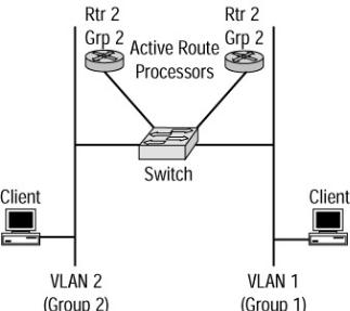
Route processors using HSRP can provide redundancy for a default gateway as well as load−balance traffic across VLANs and IP subnets (if multiple VLANs are being used, a separate HSRP standby group must be in place for each VLAN). Because route processors can be assigned as members of multiple HSRP standby groups, each standby group can have its own priority and its own active route processor. As shown in Figure 12.2, the active route processor for group 1 assigned to VLAN 1 uses route processor 2. VLAN 2 using standby group 2 will use route processor 2. In the event of a failure, the standby group will begin to use the other route processor. In this situation, load sharing will take place until a failure occurs.
Figure 12.2: VLAN 1 and VLAN 2 utilize load balancing across the multiple route processors.
246
Each standby group contains an IP address and a well−known MAC address assigned to the group. The IP address for the standby group is within the range of IP addresses belonging to the subnet or VLAN to which the route processor is providing services. The IP address cannot be assigned to any other device in the network except the standby group interfaces operating in the standby group.
Inter−Switch Link (ISL) links are used to transport VLAN information across the links to the different route processors used in each standby group. In order to pass HSRP standby group information between links for multiple VLANs, the interfaces in the group must be configured with ISL. The encapsulation format must be defined, and an IP address must be assigned to an interface.
Note |
Refer to Chapter 5 for information on configuring ISL encapsulation and assigning an IP |
|
address to an interface. |
HSRP Message Format
All route processors in the HSRP standby group send and receive HSRP messages to one another. The messages are used to determine the roles of each route processor in the group. User Datagram Protocol (UDP) utilizing TCP port 17 encapsulates the data in the data portion of the UDP packet. The packet is then sent to an all−router multicast address with a time to live (TTL) of one hop.
The fields contained in an HSRP message are:
∙Version—Indicates the HSRP version.
∙Op Code—Describes the type of message contained in the packet. The three types of messages are as follows:
♦Hello—The first and most common message, which is sent to indicate that a route processor in the standby group is functioning in the group.
♦Coup—Indicates that a route processor wants to become the active route processor.
♦Resign—Notifies the other standby group members that a route processor no longer can or will participate as the active route processor.
♦State—Indicates the current state of the route processor sending the message.
♦Hellotime—Indicates the time period in seconds between hello messages that the sending route processor sends. The default is three seconds.
♦Holdtime—Used when sending hello messages. This field indicates the length of time in seconds that the message should be considered valid. The holdtime should be at least three times the value assigned to hellotime. The default time is 10 seconds.
♦Priority—Used to elect the active and standby route processors. The route processor with the highest priority in the HSRP group wins the election and becomes the active route processor.
♦Group—Indicates the standby group number. The valid numbers are 0 to 255; 255 groups can be configured as valid HSRP groups.
♦Authentication data—Contains an eight−character clear text password that is continuously reused.
♦Virtual address—Contains the IP address of the router that is used by the HSRP group.
Just as in Spanning−Tree Protocol (STP), a route processor goes through different states before it becomes fully functional. In the next section, we’ll look at these different states and how skipping one or more of the states affects HSRP.
The HSRP States
A route processor such as a router can transition through six HSRP states. The definitions of the states are included here:
∙Initial state—All route processors begin in this state. In this starting state, HSRP is not running. The route processor can be found in this state after the power cycles or if a configuration change is applied
247