
- •Table of Contents
- •Cisco Switching Black Book
- •Introduction
- •Overview
- •Is This Book for You?
- •How to Use This Book
- •The Black Book Philosophy
- •Chapter 1: Network Switching Fundamentals
- •In Depth
- •Physical Media and Switching Types
- •A Bit of History
- •Networking Architectures
- •The Pieces of Technology
- •Repeaters
- •Hubs
- •Bridges
- •Routers
- •Switches
- •Network Design
- •Collision Domains
- •Broadcast Domains
- •Why Upgrade to Switches?
- •Switched Forwarding
- •Switched Network Bottlenecks
- •The Rule of the Network Road
- •Switched Ethernet Innovations
- •Fast Ethernet
- •Gigabit Ethernet
- •The Cisco IOS
- •Connecting to the Switch
- •Powering Up the Switch
- •The Challenges
- •Entering and Exiting Privileged EXEC Mode
- •Entering and Exiting Global Configuration Mode
- •Entering and Exiting Interface Configuration Mode
- •Entering and Exiting Subinterface Configuration Mode
- •Saving Configuration Changes
- •Chapter 2: Basic Switch Configuration
- •In Depth
- •Campus Hierarchical Switching Model
- •Access Layer
- •Distribution Layer
- •Core Layer
- •Remote Network Monitoring
- •Connecting to the Console Port
- •Console Cable Pinouts
- •Console Connectors
- •Switch IOSs
- •The IOS Configuration Modes
- •Limiting Telnet Access
- •Implementing Privilege Levels
- •Setting the Login Passwords
- •Setting Privilege Levels
- •Assigning Allowable Commands
- •Configuring the Hostname
- •Configuring the Date and Time
- •Configuring an IP Address and Netmask
- •Configuring a Default Route and Gateway
- •Configuring Port Speed and Duplex
- •Enabling SNMP Contact
- •Logging On to a Switch
- •Setting the Login and Enable Passwords
- •Changing the Console Prompt
- •Entering a Contact Name and Location Information
- •Configuring System and Time Information
- •Configuring an IP Address and Netmask
- •Configuring a Default Route and Gateway
- •Viewing the Default Routes
- •Configuring Port Speed and Duplex
- •Enabling SNMP
- •Configuring Trap Message Targets
- •Configuring the Console Port
- •Configuring Telnet
- •Configuring the Password
- •Configuring an IP Address and Default Gateway
- •Configuring SNMP
- •Configuring ROM
- •Entering ROM Configuration Mode
- •Booting ROM Mode from a Flash Device
- •Configuring SNMP
- •Configuring RMON
- •Using Set/Clear Command Set Recall Key Sequences
- •Chapter 3: WAN Switching
- •In Depth
- •WAN Transmission Media
- •Synchronous Transport Signal (STS)
- •Cisco WAN Switches
- •MGX 8200 Series
- •IGX 8400 Series
- •WAN Switch Hardware Overview
- •Cisco WAN Switch Network Topologies
- •Network Management
- •WAN Manager
- •Accessing and Setting Up IGX and BPX Switches
- •Adding New Users
- •Using the History Command
- •Displaying a Summary of All Card Modules
- •Displaying Detailed Information for a Card Module
- •Displaying the Power and Temperature of a Switch
- •Displaying the ASM Statistics for BPX
- •Configuring the ASM Setting for BPX
- •Logging Out
- •Resetting the Switch
- •Displaying Other Switches
- •Setting the Switch Name
- •Setting the Time Zone
- •Configuring the Time and Date
- •Configuring the Control and Auxiliary Ports
- •Modifying the Functions of the Control and Auxiliary Ports
- •Configuring the Printing Function
- •Configuring the LAN Interface
- •Accessing the MGX 8850 and 8220
- •Adding New Users
- •Changing Passwords
- •Assigning a Switch Hostname
- •Displaying a Summary of All Modules
- •Displaying Detailed Information for the Current Card
- •Changing the Time and Date
- •Displaying the Configuration of the Maintenance and Control Ports
- •Displaying the IP Address
- •Configuring the IP Interface
- •Displaying the Alarm Level of the Switch
- •Chapter 4: LAN Switch Architectures
- •In Depth
- •The Catalyst Crescendo Architecture
- •ASICs
- •The Crescendo Processors
- •Crescendo Logic Units
- •Other Cisco Switch Processors, Buses, ASICs, and Logic Units
- •AXIS Bus
- •CEF ASIC
- •Phoenix ASIC
- •SAGE ASIC
- •QTP ASIC
- •QMAC
- •Bridging Types
- •Source Route Bridging
- •Source Route Transparent Bridging
- •Source Route Translational Bridging
- •Transparent Bridging
- •Source Route Switching
- •Switching Paths
- •Process Switching
- •Fast Switching
- •Autonomous Switching
- •Silicon Switching
- •Optimum Switching
- •Distributed Switching
- •NetFlow Switching
- •System Message Logging
- •Loading an Image on the Supervisor Engine III
- •Booting the Supervisor Engine III from Flash
- •Setting the Boot Configuration Register
- •Configuring Cisco Express Forwarding
- •Enabling CEF
- •Disabling CEF
- •Enabling dCEF
- •Disabling dCEF
- •Disabling CEF on an Individual Interface
- •Configuring CEF Load Balancing
- •Disabling CEF Load Balancing
- •Enabling Network Accounting for CEF
- •Setting Network Accounting for CEF to Collect Packet Numbers
- •Viewing Network Accounting for CEF Statistics
- •Viewing the Adjacency Table on the 8500 GSR
- •Clearing the Adjacency Table on the 8500 GSR
- •Clearing the Server Logging Table
- •Disabling Server Logging
- •Displaying the Logging Configuration
- •Displaying System Logging Messages
- •Chapter 5: Virtual Local Area Networks
- •In Depth
- •The Flat Network of Yesterday
- •Why Use VLANs?
- •VLAN Basics
- •A Properly Switched Network
- •Switched Internetwork Security
- •Scaling with VLANs
- •VLAN Boundaries
- •VLAN Membership Types
- •Traffic Patterns Flowing through the Network
- •VLAN Trunking
- •Trunk Types
- •LAN Emulation (LANE)
- •VLAN Trunking Protocol (VTP)
- •VTP Versions
- •VTP Advertisements
- •VTP Switch Modes
- •Methods for VLAN Identification
- •Dynamic Trunking Protocol
- •InterVLAN Routing
- •Internal Route Processors
- •How InterVLAN Routing Works
- •Configuring a Static VLAN on a Catalyst 5000 Series Switch
- •Configuring Multiple VLANs on a Catalyst 5000 Series Switch
- •Creating VLANs on a Catalyst 1900EN Series
- •Assigning a Static VLAN to an Interface on a 1900EN Series
- •Viewing the VLAN Configuration on a 1900 Series
- •Viewing an Individual VLAN Configuration on a 1900 Series
- •Configuring a Trunk Port on a Cisco 5000 Series
- •Mapping VLANs to a Trunk Port
- •Configuring a Trunk Port on a Cisco 1900EN Series
- •Clearing VLANs from Trunk Links on a Cisco 5000 Series
- •Clearing VLANs from Trunk Links on a Cisco 1900EN Series
- •Verifying a Trunk Link Configuration on a 5000 Series
- •Verifying a Trunk Link Configuration on a 1900EN Series
- •Configuring the VTP Version on a Catalyst 5000 Switch
- •Configuring a VTP Domain on a Catalyst 1900 Switch
- •Setting a VTP Domain Password on a Catalyst Switch
- •Configuring a Catalyst 1900 Switch as a VTP Server
- •Configuring a Catalyst 1900 Switch as a VTP Client
- •Configuring a Catalyst 1900 Switch for Transparent Mode
- •Configuring VTP Pruning on a Catalyst 1900 Switch
- •Configuring VTP on a Set/Clear CLI Switch
- •Configuring VTP on a 1900 Cisco IOS CLI Switch
- •Verifying the VTP Configuration on a Set/Clear CLI
- •Displaying VTP Statistics
- •Configuring VTP Pruning on a Set/Clear CLI Switch
- •Disabling Pruning for Unwanted VLANs
- •Configuring IP InterVLAN Routing on an External Cisco Router
- •Configuring IPX InterVLAN Routing on an External Router
- •In Depth
- •Internal Route Processors
- •Available Route Processors
- •Routing Protocol Assignment
- •Supervisor Engine Modules
- •Supervisor Engines I and II
- •Supervisor Engine III
- •Using the Supervisor Engine
- •Etherport Modules
- •Port Security
- •Manually Configured MAC Addresses
- •Determining the Slot Number in Which a Module Resides
- •Accessing the Internal Route Processor from the Switch
- •Configuring a Hostname on the RSM
- •Assigning an IP Address and Encapsulation Type to an Ethernet Interface
- •Setting the Port Speed and Port Name on an Ethernet Interface
- •Configuring a Default Gateway on a Catalyst 5000
- •Verifying the IP Configuration on a Catalyst 5000
- •Enabling RIP on an RSM
- •Configuring InterVLAN Routing on an RSM
- •Configuring IPX InterVLAN Routing on the RSM
- •Configuring AppleTalk InterVLAN Routing on an RSM
- •Viewing the RSM Configuration
- •Assigning a MAC Address to a VLAN
- •Viewing the MAC Addresses
- •Configuring Filtering on an Ethernet Interface
- •Configuring Port Security on an Ethernet Module
- •Clearing MAC Addresses
- •Configuring the Catalyst 5000 Supervisor Engine Module
- •Changing the Management VLAN on a Supervisor Engine
- •Viewing the Supervisor Engine Configuration
- •Configuring the Cisco 2621 External Router for ISL Trunking
- •Configuring Redundancy Using HSRP
- •Chapter 7: IP Multicast
- •In Depth
- •IP Multicasting Overview
- •Broadcast
- •Unicast
- •Multicast
- •IP Multicasting Addresses
- •The Multicast IP Structure
- •Delivery of Multicast Datagrams
- •Multicast Distribution Tree
- •Multicast Forwarding
- •IGMP Protocols
- •Internet Group Management Protocol (IGMP)
- •IGMPv1
- •IGMPv2
- •Time to Live
- •Multicast at Layer 2
- •IGMP Snooping
- •Cisco Group Management Protocol
- •Router Group Management Protocol
- •GARP Multicast Registration Protocol
- •Configuring IP Multicast Routing
- •Disabling IP Multicast Routing
- •Enabling PIM on an Interface
- •Disabling PIM on an Interface
- •Configuring the Rendezvous Point
- •Adding a Router to a Multicast Group
- •Configuring a Router to Be a Static Multicast Group Member
- •Restricting Access to a Multicast Group
- •Changing the IGMP Version
- •Configuring Multicast Groups
- •Removing Multicast Groups
- •Configuring Multicast Router Ports
- •Displaying Multicast Routers
- •Removing the Multicast Router
- •Configuring IGMP Snooping
- •Disabling IGMP Snooping
- •Displaying IGMP Statistics
- •Displaying Multicast Routers Learned from IGMP
- •Displaying IGMP Multicast Groups
- •Configuring CGMP
- •Disabling CGMP
- •Displaying CGMP Statistics
- •Configuring RGMP on the Switch
- •Disabling RGMP on the Switch
- •Configuring RGMP on the Router
- •Disabling RGMP on the Router
- •Displaying RGMP Groups
- •Displaying RGMP VLAN Statistics
- •Configuring GMRP
- •Disabling GMRP
- •Enabling GMRP on Individual Ports
- •Disabling GMRP on Individual Ports
- •Configuring GMRP Registration
- •Displaying the GMRP Configuration
- •Setting GMRP Timers
- •Displaying GMRP Timers
- •Disabling Multicast Suppression
- •Chapter 8: WAN Cell Switching
- •In Depth
- •ATM Overview
- •LANE
- •ATM Protocols
- •ATM Circuit Switching
- •ATM Cells
- •The ATM Switch and ATM Endpoints
- •The ATM Reference Model
- •Specifying ATM Connections
- •ATM Addressing
- •Local Area Network Emulation (LANE)
- •LANE Components
- •Integrated Local Management Interface (ILMI)
- •LANE Communication
- •LANE Configuration Guidelines
- •How LANE Works
- •Implementing LANE
- •Configuring ATM on the 5000 Switch
- •Connecting in an ATM Network
- •Monitoring and Maintaining LANE
- •Accessing the ATM LANE Module
- •Displaying the Selector Field
- •Configuring the LES/BUS
- •Verifying the LES/BUS Configuration
- •Configuring a LEC for an ELAN
- •Verifying a LEC Configuration on an ELAN
- •Configuring the LECS
- •Viewing the LANE Database
- •Binding the LECS Address to an Interface
- •Verifying the LECS Configuration
- •Chapter 9: LightStream Switches
- •In Depth
- •LightStream 100
- •LightStream 1010
- •LightStream 2020
- •Neighborhood Discovery Function
- •Virtual Path Connections
- •LightStream Troubleshooting Tools
- •LightStream Boot Process
- •Supported Troubleshooting Protocols
- •Snooping Mechanisms
- •Multiprotocol Over ATM
- •Configuring the Hostname
- •Configuring an Enable Password
- •Configuring the Processor Card Ethernet Interface
- •Configuring Virtual Private Tunnels
- •Verifying an ATM Interface Connection Status
- •Viewing the Configured Virtual Connections
- •Configuring the LECS ATM Address on a LightStream 1010 Switch
- •Configuring the Advertised LECS Address
- •Viewing the LANE Configuration
- •Viewing the Installed Modules
- •Configuring the MPC
- •Configuring the MPS
- •Changing the MPS Variables
- •Monitoring the MPS
- •Enabling ILMI Autoconfiguration
- •Configuring LANE on a LightStream 1010
- •Powering on the LightStream 100 ATM Switch
- •Configuring the LS100 Switch
- •Recovering a Lost Password
- •Chapter 10: Layer 2 Redundant Links
- •In Depth
- •Layer 2 Switching Overview
- •Frames
- •Broadcast and Multicast Frames
- •Unknown Unicasts
- •Layer 2 Network Loops
- •Danger! Data Loops!
- •STP Root Bridges
- •Bridge Protocol Data Units
- •Root Bridge Selection
- •Spanning Tree Convergence Time
- •STP Port States
- •EtherChannel
- •Link Failure
- •Port Aggregation Protocol
- •Fast Convergence Components of STP
- •PortFast
- •UplinkFast
- •BackboneFast
- •Viewing the STP Configuration on a Command Line Switch
- •Configuring the STP Root Switch
- •Configuring the STP Secondary Root Switch
- •Verifying the VLAN Priority Settings
- •Preparing to Enable EtherChannel
- •Verifying the EtherChannel Configuration
- •Defining an EtherChannel Administrative Group
- •Viewing an EtherChannel Administrative Group
- •Identifying the Template Port
- •Verifying the EtherChannel Configuration on a Command Line Interface IOS
- •Verifying the PortFast Configuration
- •Verifying the UplinkFast Configuration
- •Viewing the BackboneFast Configuration
- •Chapter 11: Multilayer Switching
- •In Depth
- •How MLS Works
- •MLS Components
- •MLS Flows
- •Access List Flow Masks
- •MLS Troubleshooting Notes
- •Configuring MLS
- •MLS Cache
- •Aging Timers
- •VLAN ID
- •VTP Domain
- •Management Interfaces
- •Configuring an External MLS Route Processor
- •Assigning a VLAN ID
- •Adding an MLS Interface to a VTP Domain
- •Enabling MLS on an Individual Interface
- •Disabling MLS on an External Router Interface
- •Configuring the MLS Switch Engine
- •Disabling MLS on a Catalyst 6000
- •Disabling MLS on a Catalyst 5000
- •Configuring the MLS Cache on the Catalyst 5000
- •Configuring Fast Aging on a Catalyst 5000
- •Configuring Fast Aging on a Catalyst 6000
- •Disabling Fast Aging on a Catalyst 6000
- •Configuring Long Aging on the Catalyst 6000
- •Disabling Long Aging on the Catalyst 6000
- •Configuring Normal Aging on the Catalyst 6000
- •Disabling Normal Aging on the Catalyst 6000
- •Assigning MLS Management to an Interface on the Catalyst 5000
- •Disabling MLS Management on an Interface on the Catalyst 5000
- •Monitoring and Viewing the MLS Configuration
- •Viewing the MLS Aging Configuration on a Catalyst 6000
- •Displaying the IP MLS Configuration
- •Displaying MLS VTP Domain Information
- •Viewing the MLS VLAN Interface Information
- •Viewing MLS Statistics on the Catalyst 5000
- •Viewing MLS Statistics on the Catalyst 6000
- •Viewing MLS Entries
- •Chapter 12: Hot Standby Routing Protocol
- •In Depth
- •Routing Problems
- •Routing Information Protocol
- •Proxy ARP
- •ICMP Router Discovery Protocol
- •The Solution
- •HSRP Message Format
- •The HSRP States
- •HSRP Configuration
- •HSRP Interface Tracking
- •Opening a Session on an Internal Route Processor
- •Entering Configuration Mode on an RSM
- •Enabling HSRP and Assigning an IP Address to a Standby Group
- •Assigning an HSRP Interface Priority
- •Assigning a Preempt Delay to a Standby Group
- •Removing a Preempt Delay from a Standby Group
- •Setting the HSRP Hello and Hold Timers
- •Removing the HSRP Hello and Hold Timers
- •Configuring Two RSFC Interfaces as One HSRP Group
- •Enabling Interface Tracking
- •Using the show standby Command
- •Using the debug Command
- •Chapter 13: Policy Networking
- •In Depth
- •Access Security Policies
- •Core Layer Policies
- •Distribution Layer Policies
- •Security at the Access Layer
- •Configuring Passwords
- •Limiting Telnet Access
- •Implementing Privilege Levels
- •Configuring Banner Messages
- •Physical Device Security
- •Port Security
- •VLAN Management
- •Creating a Standard Access List
- •Creating an Extended Access List
- •Implementing Privilege Levels on a 1900EN
- •Configuring Banner Messages
- •Enabling HTTP Access
- •Enabling Port Security
- •Displaying the MAC Address Table
- •Chapter 14: Web Management
- •In Depth
- •Standard and Enterprise Edition CVSM
- •CVSM Client Requirements
- •CVSM Access Levels
- •CVSM Default Home Page
- •The Switch Image
- •Configuring the Switch with an IP Address and Setting the Default Web Administration Port
- •Connecting to the Web Management Console
- •Configuring the Switch Port Analyzer
- •Chapter 15: The Standard Edition IOS
- •In Depth
- •The 1900 and 2820 Series Switches
- •Main Menu Choices
- •[C] Console Settings
- •[A] Port Addressing
- •[R] Multicast Registration
- •Configuring Network Settings on the 1900 and 2820 Series
- •Configuring Broadcast Storm Control on Switch Ports
- •Configuring SNMP on the 1900 Series
- •Configuring Port Monitoring on the Standard Edition IOS
- •Configuring VLANs on the Standard Edition IOS
- •Configuring Spanning Tree Protocol
- •Chapter 16: Switch Troubleshooting
- •In Depth
- •Hardware Troubleshooting
- •No Power
- •POST
- •Indicator Lights
- •Switch Cabling
- •Cable Problems
- •Switch Troubleshooting Tools
- •CiscoWorks for Switched Internetworks
- •IOS Software Troubleshooting Commands
- •Viewing the Set/Clear IOS Configuration
- •Viewing the VTP Domain Configuration on a Set/Clear IOS
- •Viewing Port Statistics on a Set/Clear IOS
- •Launching the Diagnostic Console on a Cisco 1900 or 2820 Series Switch
- •Using the Diagnostic Console to Upgrade the Firmware on a Cisco 1900 or 2820 Series Switch
- •Using the Diagnostic Console for Debugging the Firmware and Hardware
- •Appendix A: Study Resources
- •Books
- •Cisco Group Study and Users Groups
- •Online Resources
- •Asynchronous Transfer Mode
- •Cisco IOS
- •Hot Standby Router Protocol
- •IP Multicast
- •Multilayer Switching
- •Quality of Service
- •Spanning Tree Protocol
- •TACACS+
- •VLANs
- •Standards Organizations
- •Cisco Job Search Sites
- •Overview
- •Appendix C: The Cisco Consultant
- •Overview
- •Establishing Credibility
- •Come Off As an Expert
- •Designing a Solution
- •Estimating the Cost
- •Presenting the Final Proposal and Creating Expectations
- •Contracting
- •Document, Document, Document
- •The Way to Fail
- •Failing to Be There When Promised, or Rushing through the Job
- •Failing to Manage Your Time
- •Assuming You Know What the Customer Needs
- •Failing to Take Responsibility
- •Conclusion
- •Required Equipment
- •Lab Objectives
- •Possible Solution
- •The 1912 Basic Configuration
- •The Catalyst 5000 Basic Configuration
- •Configuring the Cisco 2621 Interface for ISL Trunking
- •Appendix E: Switch Features
- •Access Layer Switches
- •Cisco Catalyst 1900
- •Cisco Catalyst 2820
- •Cisco Catalyst 2900
- •Cisco Catalyst 3000
- •Cisco Catalyst 3500 Series XL
- •Cisco Catalyst 3900 Series
- •Distribution Layer Switches
- •Cisco Catalyst 4000 Series
- •Catalyst 5000 Series
- •Catalyst 6000 Series
- •Core Layer/WAN Switches
- •Cisco Catalyst 8400 Series
- •Cisco Catalyst 8500 Series
- •BPX 8600 Series
- •MGX 8800 Series
- •12000 Series Gigabit Switch Routers

Chapter 4: LAN Switch Architectures
In Depth
Knowing the internal architectures of networking devices can be a great asset when you’re working with Cisco switches. Knowing how the internal components work together, as well as how Application−Specific Integrated Circuits (ASICs) and CPUs are used, can give you an advantage in determining what Cisco device will work best at every point in the network.
The Catalyst Crescendo Architecture
When you’re looking at the architecture of the switch, ASICs are among the most important components. ASICs are very fast and relatively inexpensive silicon chips that do one or two specific tasks faster than a processor can perform those same functions. These chips have some advantages over a processor but lack functions such as filtering and advanced management functions, and they have limited support for bridging modes. ASICs make today’s switches less expensive than processor−based switches. Processor−based switches are still available, but they are expensive and limited in the number of tasks they can take on and still maintain reliable and acceptable limits of throughput.
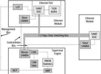
The Set/Clear command−based Command Line Interface (CLI) switches (also known as Crescendo Interface switches) found in the Cisco Catalyst 2900G, 5000, 5500, 6000, and 6500 series of switches, give the best example of how the Broadcast and Unknown Server (BUS), ASICs, Arbiters, and logic units work inside the switch. Let’s look at Figure 4.1, which shows a diagram of the ASICs and processors found inside a Cisco 5000 series switch. We’ll examine these components and then look at several other ASICs that are for more specialized or earlier model Cisco Catalyst switches.
Figure 4.1: The architecture of the Cisco Catalyst 5000 series switch.
First, we need to look at the components involved: the ASICs, Catalyst processors, bus, and other units of logic. Let’s begin by examining each of the BUSs; then we will define the ASICs shown in Figure 4.1.
BUS
Every switch must have at least two interfaces. But what fun would just two be? Today’s switches can have hundreds of ports. The BUS connects all these interfaces—it moves frames from one interface to the other. All these frames require an arbitration process using processors, ASICs, and logic units to make sure data doesn’t slip out the wrong port or ports.
68

Single BUS vs. Crossbar Matrix
A single−BUS architecture is pretty simple: One BUS connects all the ports together. This setup creates a bandwidth problem called a blocking architecture, or what the networking industry likes to call over−subscription. Over−subscription is characterized as a condition in which the total bandwidth of all the ports on the switch is greater than the capacity of the switching fabric or backplane. As a result, data is held up at the port because the tunnel−through switch is too small. Examples of Cisco switches with a single−BUS architecture are the Cisco Catalyst 1900, 2820, 3000, and 5000 series.
A cross−bar matrix is used to solve the problems of a single BUS architecture by creating a multiple BUS architecture in which more than one BUS services the switch ports. In this architecture, the BUS can handle all the data the ports can possibly send—and more. It is sometimes referred to as a non−blocking architecture, and it requires a very sophisticated arbitration scheme.
Tip The switching fabric is the “highway” the data takes from the point of entry to the port or ports from which the data exits.
Each switch employs some kind of queuing method in order to solve blocking problems. An Ethernet interface may receive data when the port does not have access to the BUS. In this situation, the port has a buffer in which it stores the frame it receives until the BUS can process it. The frame uses queuing to determine which frame will be processed next. Let’s look at the three queuing components: input queuing, output queuing, and shared buffering.
Input Queuing
Input queuing is the simpler of the two forms of queuing. The frame is buffered into the port’s buffer until it becomes its turn to enter the bus. When the frame enters the bus, the exit port must be free to allow the frame to exit. If another frame is exiting the port, a condition called head−of−line blocking occurs: The frame is dropped because it was blocked by other data.
Output Queuing
Output queuing can be used with input queuing; it allows the frame to be buffered on the outbound port if other data is in the way. This is a way to resolve head−of−line blocking, but if a large burst of frames occurs, head−of−line blocking still can occur. The problem of large bursts can be resolved by using shared buffering. All the Cisco Catalyst switches (with the exception of the 1900 and 2820 series) use both input and output queuing.
Shared Buffering
Although there is no sure way to stop head−of−line blocking, shared buffering can be used in a switch as a safeguard. Shared buffering is a derivative of output queuing and provides each port with access to one large buffer instead of smaller, individual buffering spaces. If a frame is placed in this buffer, the frame is extracted from the shared memory buffer and forwarded. This method is used on the 1900 and 2820 series of Cisco Catalyst switches.
ASICs
The ASICs shown in Figure 4.1 are used in the Catalyst 5000 series Supervisor Engine and an Ethernet Module. Let’s take a look at each:
∙Encoded Address Recognition Logic (EARL) ASIC
∙Encoded Address Recognition Logic Plus (EARL+) ASIC
∙Synergy Advanced Interface and Network Termination (SAINT) ASIC
69

∙ Synergy Advanced Multipurpose Bus Arbiter (SAMBA) ASIC
EARL ASIC
The Encoded Address Recognition Logic (EARL) ASIC performs functions that are very similar to those of the Content Addressable Memory (CAM) table. Switches use this CAM to make filtering and forwarding decisions. The EARL ASIC connects directly to the data switching bus, allowing the ASIC access to all the frames that cross the switching fabric. The switch makes forwarding decisions based on the destination Media Access Control (MAC) address.
Note The CAM table contains the MAC address of the interfaces connected to the port and the time the switch last read a frame from that source port and address. The CAM table receives updated information by examining frames it receives from a segment; it then updates the table with the source MAC address from the frame.
The EARL ASIC aids in building a table containing all the information the switch has extracted from incoming frames. This information includes the source MAC address, the port of arrival, the virtual LAN (VLAN) membership of the port of arrival, and the time the frame was received. This table can contain up to 128,000 entries. Entries in the table are removed after the time to live (TTL) has expired. The default TTL at which entries are removed is 300 seconds; this time can be set from 1 to 20 minutes.
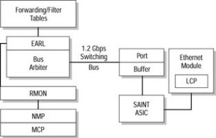
The EARL ASIC tags each frame as it arrives at the switch before the frame is buffered. This tagging includes the source port’s identity, the VLAN, and a checksum. This tagging should not be confused with the tagging used in trunking for Inter−Switch Link (ISL) or 802.1Q, discussed in Chapter 5. The tagging the EARL places in the frame is removed before the frame exits the switch. The EARL ASIC’s placement is shown in Figure 4.2.
Figure 4.2: EARL ASIC placement on the Crescendo architecture.
EARL+ ASIC
The Encoded Address Recognition Logic Plus (EARL+) ASIC allows the EARL to support Token Ring line modules. The EARL+ ASIC is an enhancement to the EARL ASIC and is used on the Supervisor Engine III Module.
SAINT ASIC
The Synergy Advanced Interface and Network Termination (SAINT) ASIC allows a switch interface to support both half−duplex and full−duplex Ethernet. This ASIC has a second responsibility to handle frame encapsulation and de−encapsulation, and gathering statistics for trunked ports.
SAMBA ASIC
The Synergy Advanced Multipurpose Bus Arbiter (SAMBA) ASIC and the EARL ASIC work in tandem to let ports access the bus, thus allowing frames to be forwarded correctly. Both the Supervisor Engine and the installed line modules utilize this ASIC; it can support up to 13 separate line modules.
70
This ASIC operates in either master or slave mode. In master mode, the ASIC allows ports access to the bus based on a priority level of normal, high, or critical. In slave mode, each port must post a request to each SAMBA ASIC, negotiate local port decisions, and arbitrate requests with the Supervisor Engine’s SAMBA ASIC.
The Crescendo Processors
Although we have ASICs to do some of the hard work of the processors, processors still must be involved to handle the more dynamic administrative items. They carry the intelligence behind the frame−switching process. Inside the Crescendo Interface Internetwork Operating System (IOS) switches, the processors connect to a bus; the bus in turn connects to other ASICs and processors inside the switch. In the following sections, I will examine the processors listed here and their assigned functions. You will find these processors in the Crescendo Interface Catalyst switches:
∙Line Module Communication Processor (LCP)
∙Master Communication Processor (MCP)
∙Network Management Processor (NMP)
LCP
The Line Module Communication Processor (LCP) can be found on each line module in the switch. This ASIC’s responsibility is to provide communications for access to the Master Communication Processor (MCP) located on the Supervisor Engine.
The LCP automatically boots from read−only memory (ROM) and is an 8051 processor. Immediately upon boot up, the ASIC forwards an information package called a Resetack to the MCP. Resetack includes information regarding the switch’s boot diagnostics and module information. This information is then forwarded from the MCP to the Network Management Processor (NMP).
MCP
The Master Communication Processor (MCP), which is sometimes called the Management Control Processor, uses a serial management bus to communicate between the NMP on the Supervisor Engine module and the LCP on the individual line cards located in the switch. The MCP also has a secondary job: to test and check the configuration of the local ports, control of local ports, downloading of runtime code, and performing continuous port diagnostics. This ASIC handles the diagnostics and obtains the usage statistics of the on−board memory, ASICs, Local Target Logic (LTL), and Color Blocking Logic (CBL).
NMP
The Network Management Processor (NMP) is used to control the system hardware, configuration, switch management, the Spanning−Tree Protocol (STP) (discussed in Chapter 10), and diagnostic functions.
Crescendo Logic Units
Logic units provide logic−based forwarding by VLAN, MAC address, or port assignment. The Catalyst Crescendo Interface switches contain the following logic units:
∙Arbiter (ARB)
∙Local Target Logic (LTL)
∙Color Blocking Logic (CBL)
∙Remote Network Monitoring (RMN)
71