
- •Table of Contents
- •Cisco Switching Black Book
- •Introduction
- •Overview
- •Is This Book for You?
- •How to Use This Book
- •The Black Book Philosophy
- •Chapter 1: Network Switching Fundamentals
- •In Depth
- •Physical Media and Switching Types
- •A Bit of History
- •Networking Architectures
- •The Pieces of Technology
- •Repeaters
- •Hubs
- •Bridges
- •Routers
- •Switches
- •Network Design
- •Collision Domains
- •Broadcast Domains
- •Why Upgrade to Switches?
- •Switched Forwarding
- •Switched Network Bottlenecks
- •The Rule of the Network Road
- •Switched Ethernet Innovations
- •Fast Ethernet
- •Gigabit Ethernet
- •The Cisco IOS
- •Connecting to the Switch
- •Powering Up the Switch
- •The Challenges
- •Entering and Exiting Privileged EXEC Mode
- •Entering and Exiting Global Configuration Mode
- •Entering and Exiting Interface Configuration Mode
- •Entering and Exiting Subinterface Configuration Mode
- •Saving Configuration Changes
- •Chapter 2: Basic Switch Configuration
- •In Depth
- •Campus Hierarchical Switching Model
- •Access Layer
- •Distribution Layer
- •Core Layer
- •Remote Network Monitoring
- •Connecting to the Console Port
- •Console Cable Pinouts
- •Console Connectors
- •Switch IOSs
- •The IOS Configuration Modes
- •Limiting Telnet Access
- •Implementing Privilege Levels
- •Setting the Login Passwords
- •Setting Privilege Levels
- •Assigning Allowable Commands
- •Configuring the Hostname
- •Configuring the Date and Time
- •Configuring an IP Address and Netmask
- •Configuring a Default Route and Gateway
- •Configuring Port Speed and Duplex
- •Enabling SNMP Contact
- •Logging On to a Switch
- •Setting the Login and Enable Passwords
- •Changing the Console Prompt
- •Entering a Contact Name and Location Information
- •Configuring System and Time Information
- •Configuring an IP Address and Netmask
- •Configuring a Default Route and Gateway
- •Viewing the Default Routes
- •Configuring Port Speed and Duplex
- •Enabling SNMP
- •Configuring Trap Message Targets
- •Configuring the Console Port
- •Configuring Telnet
- •Configuring the Password
- •Configuring an IP Address and Default Gateway
- •Configuring SNMP
- •Configuring ROM
- •Entering ROM Configuration Mode
- •Booting ROM Mode from a Flash Device
- •Configuring SNMP
- •Configuring RMON
- •Using Set/Clear Command Set Recall Key Sequences
- •Chapter 3: WAN Switching
- •In Depth
- •WAN Transmission Media
- •Synchronous Transport Signal (STS)
- •Cisco WAN Switches
- •MGX 8200 Series
- •IGX 8400 Series
- •WAN Switch Hardware Overview
- •Cisco WAN Switch Network Topologies
- •Network Management
- •WAN Manager
- •Accessing and Setting Up IGX and BPX Switches
- •Adding New Users
- •Using the History Command
- •Displaying a Summary of All Card Modules
- •Displaying Detailed Information for a Card Module
- •Displaying the Power and Temperature of a Switch
- •Displaying the ASM Statistics for BPX
- •Configuring the ASM Setting for BPX
- •Logging Out
- •Resetting the Switch
- •Displaying Other Switches
- •Setting the Switch Name
- •Setting the Time Zone
- •Configuring the Time and Date
- •Configuring the Control and Auxiliary Ports
- •Modifying the Functions of the Control and Auxiliary Ports
- •Configuring the Printing Function
- •Configuring the LAN Interface
- •Accessing the MGX 8850 and 8220
- •Adding New Users
- •Changing Passwords
- •Assigning a Switch Hostname
- •Displaying a Summary of All Modules
- •Displaying Detailed Information for the Current Card
- •Changing the Time and Date
- •Displaying the Configuration of the Maintenance and Control Ports
- •Displaying the IP Address
- •Configuring the IP Interface
- •Displaying the Alarm Level of the Switch
- •Chapter 4: LAN Switch Architectures
- •In Depth
- •The Catalyst Crescendo Architecture
- •ASICs
- •The Crescendo Processors
- •Crescendo Logic Units
- •Other Cisco Switch Processors, Buses, ASICs, and Logic Units
- •AXIS Bus
- •CEF ASIC
- •Phoenix ASIC
- •SAGE ASIC
- •QTP ASIC
- •QMAC
- •Bridging Types
- •Source Route Bridging
- •Source Route Transparent Bridging
- •Source Route Translational Bridging
- •Transparent Bridging
- •Source Route Switching
- •Switching Paths
- •Process Switching
- •Fast Switching
- •Autonomous Switching
- •Silicon Switching
- •Optimum Switching
- •Distributed Switching
- •NetFlow Switching
- •System Message Logging
- •Loading an Image on the Supervisor Engine III
- •Booting the Supervisor Engine III from Flash
- •Setting the Boot Configuration Register
- •Configuring Cisco Express Forwarding
- •Enabling CEF
- •Disabling CEF
- •Enabling dCEF
- •Disabling dCEF
- •Disabling CEF on an Individual Interface
- •Configuring CEF Load Balancing
- •Disabling CEF Load Balancing
- •Enabling Network Accounting for CEF
- •Setting Network Accounting for CEF to Collect Packet Numbers
- •Viewing Network Accounting for CEF Statistics
- •Viewing the Adjacency Table on the 8500 GSR
- •Clearing the Adjacency Table on the 8500 GSR
- •Clearing the Server Logging Table
- •Disabling Server Logging
- •Displaying the Logging Configuration
- •Displaying System Logging Messages
- •Chapter 5: Virtual Local Area Networks
- •In Depth
- •The Flat Network of Yesterday
- •Why Use VLANs?
- •VLAN Basics
- •A Properly Switched Network
- •Switched Internetwork Security
- •Scaling with VLANs
- •VLAN Boundaries
- •VLAN Membership Types
- •Traffic Patterns Flowing through the Network
- •VLAN Trunking
- •Trunk Types
- •LAN Emulation (LANE)
- •VLAN Trunking Protocol (VTP)
- •VTP Versions
- •VTP Advertisements
- •VTP Switch Modes
- •Methods for VLAN Identification
- •Dynamic Trunking Protocol
- •InterVLAN Routing
- •Internal Route Processors
- •How InterVLAN Routing Works
- •Configuring a Static VLAN on a Catalyst 5000 Series Switch
- •Configuring Multiple VLANs on a Catalyst 5000 Series Switch
- •Creating VLANs on a Catalyst 1900EN Series
- •Assigning a Static VLAN to an Interface on a 1900EN Series
- •Viewing the VLAN Configuration on a 1900 Series
- •Viewing an Individual VLAN Configuration on a 1900 Series
- •Configuring a Trunk Port on a Cisco 5000 Series
- •Mapping VLANs to a Trunk Port
- •Configuring a Trunk Port on a Cisco 1900EN Series
- •Clearing VLANs from Trunk Links on a Cisco 5000 Series
- •Clearing VLANs from Trunk Links on a Cisco 1900EN Series
- •Verifying a Trunk Link Configuration on a 5000 Series
- •Verifying a Trunk Link Configuration on a 1900EN Series
- •Configuring the VTP Version on a Catalyst 5000 Switch
- •Configuring a VTP Domain on a Catalyst 1900 Switch
- •Setting a VTP Domain Password on a Catalyst Switch
- •Configuring a Catalyst 1900 Switch as a VTP Server
- •Configuring a Catalyst 1900 Switch as a VTP Client
- •Configuring a Catalyst 1900 Switch for Transparent Mode
- •Configuring VTP Pruning on a Catalyst 1900 Switch
- •Configuring VTP on a Set/Clear CLI Switch
- •Configuring VTP on a 1900 Cisco IOS CLI Switch
- •Verifying the VTP Configuration on a Set/Clear CLI
- •Displaying VTP Statistics
- •Configuring VTP Pruning on a Set/Clear CLI Switch
- •Disabling Pruning for Unwanted VLANs
- •Configuring IP InterVLAN Routing on an External Cisco Router
- •Configuring IPX InterVLAN Routing on an External Router
- •In Depth
- •Internal Route Processors
- •Available Route Processors
- •Routing Protocol Assignment
- •Supervisor Engine Modules
- •Supervisor Engines I and II
- •Supervisor Engine III
- •Using the Supervisor Engine
- •Etherport Modules
- •Port Security
- •Manually Configured MAC Addresses
- •Determining the Slot Number in Which a Module Resides
- •Accessing the Internal Route Processor from the Switch
- •Configuring a Hostname on the RSM
- •Assigning an IP Address and Encapsulation Type to an Ethernet Interface
- •Setting the Port Speed and Port Name on an Ethernet Interface
- •Configuring a Default Gateway on a Catalyst 5000
- •Verifying the IP Configuration on a Catalyst 5000
- •Enabling RIP on an RSM
- •Configuring InterVLAN Routing on an RSM
- •Configuring IPX InterVLAN Routing on the RSM
- •Configuring AppleTalk InterVLAN Routing on an RSM
- •Viewing the RSM Configuration
- •Assigning a MAC Address to a VLAN
- •Viewing the MAC Addresses
- •Configuring Filtering on an Ethernet Interface
- •Configuring Port Security on an Ethernet Module
- •Clearing MAC Addresses
- •Configuring the Catalyst 5000 Supervisor Engine Module
- •Changing the Management VLAN on a Supervisor Engine
- •Viewing the Supervisor Engine Configuration
- •Configuring the Cisco 2621 External Router for ISL Trunking
- •Configuring Redundancy Using HSRP
- •Chapter 7: IP Multicast
- •In Depth
- •IP Multicasting Overview
- •Broadcast
- •Unicast
- •Multicast
- •IP Multicasting Addresses
- •The Multicast IP Structure
- •Delivery of Multicast Datagrams
- •Multicast Distribution Tree
- •Multicast Forwarding
- •IGMP Protocols
- •Internet Group Management Protocol (IGMP)
- •IGMPv1
- •IGMPv2
- •Time to Live
- •Multicast at Layer 2
- •IGMP Snooping
- •Cisco Group Management Protocol
- •Router Group Management Protocol
- •GARP Multicast Registration Protocol
- •Configuring IP Multicast Routing
- •Disabling IP Multicast Routing
- •Enabling PIM on an Interface
- •Disabling PIM on an Interface
- •Configuring the Rendezvous Point
- •Adding a Router to a Multicast Group
- •Configuring a Router to Be a Static Multicast Group Member
- •Restricting Access to a Multicast Group
- •Changing the IGMP Version
- •Configuring Multicast Groups
- •Removing Multicast Groups
- •Configuring Multicast Router Ports
- •Displaying Multicast Routers
- •Removing the Multicast Router
- •Configuring IGMP Snooping
- •Disabling IGMP Snooping
- •Displaying IGMP Statistics
- •Displaying Multicast Routers Learned from IGMP
- •Displaying IGMP Multicast Groups
- •Configuring CGMP
- •Disabling CGMP
- •Displaying CGMP Statistics
- •Configuring RGMP on the Switch
- •Disabling RGMP on the Switch
- •Configuring RGMP on the Router
- •Disabling RGMP on the Router
- •Displaying RGMP Groups
- •Displaying RGMP VLAN Statistics
- •Configuring GMRP
- •Disabling GMRP
- •Enabling GMRP on Individual Ports
- •Disabling GMRP on Individual Ports
- •Configuring GMRP Registration
- •Displaying the GMRP Configuration
- •Setting GMRP Timers
- •Displaying GMRP Timers
- •Disabling Multicast Suppression
- •Chapter 8: WAN Cell Switching
- •In Depth
- •ATM Overview
- •LANE
- •ATM Protocols
- •ATM Circuit Switching
- •ATM Cells
- •The ATM Switch and ATM Endpoints
- •The ATM Reference Model
- •Specifying ATM Connections
- •ATM Addressing
- •Local Area Network Emulation (LANE)
- •LANE Components
- •Integrated Local Management Interface (ILMI)
- •LANE Communication
- •LANE Configuration Guidelines
- •How LANE Works
- •Implementing LANE
- •Configuring ATM on the 5000 Switch
- •Connecting in an ATM Network
- •Monitoring and Maintaining LANE
- •Accessing the ATM LANE Module
- •Displaying the Selector Field
- •Configuring the LES/BUS
- •Verifying the LES/BUS Configuration
- •Configuring a LEC for an ELAN
- •Verifying a LEC Configuration on an ELAN
- •Configuring the LECS
- •Viewing the LANE Database
- •Binding the LECS Address to an Interface
- •Verifying the LECS Configuration
- •Chapter 9: LightStream Switches
- •In Depth
- •LightStream 100
- •LightStream 1010
- •LightStream 2020
- •Neighborhood Discovery Function
- •Virtual Path Connections
- •LightStream Troubleshooting Tools
- •LightStream Boot Process
- •Supported Troubleshooting Protocols
- •Snooping Mechanisms
- •Multiprotocol Over ATM
- •Configuring the Hostname
- •Configuring an Enable Password
- •Configuring the Processor Card Ethernet Interface
- •Configuring Virtual Private Tunnels
- •Verifying an ATM Interface Connection Status
- •Viewing the Configured Virtual Connections
- •Configuring the LECS ATM Address on a LightStream 1010 Switch
- •Configuring the Advertised LECS Address
- •Viewing the LANE Configuration
- •Viewing the Installed Modules
- •Configuring the MPC
- •Configuring the MPS
- •Changing the MPS Variables
- •Monitoring the MPS
- •Enabling ILMI Autoconfiguration
- •Configuring LANE on a LightStream 1010
- •Powering on the LightStream 100 ATM Switch
- •Configuring the LS100 Switch
- •Recovering a Lost Password
- •Chapter 10: Layer 2 Redundant Links
- •In Depth
- •Layer 2 Switching Overview
- •Frames
- •Broadcast and Multicast Frames
- •Unknown Unicasts
- •Layer 2 Network Loops
- •Danger! Data Loops!
- •STP Root Bridges
- •Bridge Protocol Data Units
- •Root Bridge Selection
- •Spanning Tree Convergence Time
- •STP Port States
- •EtherChannel
- •Link Failure
- •Port Aggregation Protocol
- •Fast Convergence Components of STP
- •PortFast
- •UplinkFast
- •BackboneFast
- •Viewing the STP Configuration on a Command Line Switch
- •Configuring the STP Root Switch
- •Configuring the STP Secondary Root Switch
- •Verifying the VLAN Priority Settings
- •Preparing to Enable EtherChannel
- •Verifying the EtherChannel Configuration
- •Defining an EtherChannel Administrative Group
- •Viewing an EtherChannel Administrative Group
- •Identifying the Template Port
- •Verifying the EtherChannel Configuration on a Command Line Interface IOS
- •Verifying the PortFast Configuration
- •Verifying the UplinkFast Configuration
- •Viewing the BackboneFast Configuration
- •Chapter 11: Multilayer Switching
- •In Depth
- •How MLS Works
- •MLS Components
- •MLS Flows
- •Access List Flow Masks
- •MLS Troubleshooting Notes
- •Configuring MLS
- •MLS Cache
- •Aging Timers
- •VLAN ID
- •VTP Domain
- •Management Interfaces
- •Configuring an External MLS Route Processor
- •Assigning a VLAN ID
- •Adding an MLS Interface to a VTP Domain
- •Enabling MLS on an Individual Interface
- •Disabling MLS on an External Router Interface
- •Configuring the MLS Switch Engine
- •Disabling MLS on a Catalyst 6000
- •Disabling MLS on a Catalyst 5000
- •Configuring the MLS Cache on the Catalyst 5000
- •Configuring Fast Aging on a Catalyst 5000
- •Configuring Fast Aging on a Catalyst 6000
- •Disabling Fast Aging on a Catalyst 6000
- •Configuring Long Aging on the Catalyst 6000
- •Disabling Long Aging on the Catalyst 6000
- •Configuring Normal Aging on the Catalyst 6000
- •Disabling Normal Aging on the Catalyst 6000
- •Assigning MLS Management to an Interface on the Catalyst 5000
- •Disabling MLS Management on an Interface on the Catalyst 5000
- •Monitoring and Viewing the MLS Configuration
- •Viewing the MLS Aging Configuration on a Catalyst 6000
- •Displaying the IP MLS Configuration
- •Displaying MLS VTP Domain Information
- •Viewing the MLS VLAN Interface Information
- •Viewing MLS Statistics on the Catalyst 5000
- •Viewing MLS Statistics on the Catalyst 6000
- •Viewing MLS Entries
- •Chapter 12: Hot Standby Routing Protocol
- •In Depth
- •Routing Problems
- •Routing Information Protocol
- •Proxy ARP
- •ICMP Router Discovery Protocol
- •The Solution
- •HSRP Message Format
- •The HSRP States
- •HSRP Configuration
- •HSRP Interface Tracking
- •Opening a Session on an Internal Route Processor
- •Entering Configuration Mode on an RSM
- •Enabling HSRP and Assigning an IP Address to a Standby Group
- •Assigning an HSRP Interface Priority
- •Assigning a Preempt Delay to a Standby Group
- •Removing a Preempt Delay from a Standby Group
- •Setting the HSRP Hello and Hold Timers
- •Removing the HSRP Hello and Hold Timers
- •Configuring Two RSFC Interfaces as One HSRP Group
- •Enabling Interface Tracking
- •Using the show standby Command
- •Using the debug Command
- •Chapter 13: Policy Networking
- •In Depth
- •Access Security Policies
- •Core Layer Policies
- •Distribution Layer Policies
- •Security at the Access Layer
- •Configuring Passwords
- •Limiting Telnet Access
- •Implementing Privilege Levels
- •Configuring Banner Messages
- •Physical Device Security
- •Port Security
- •VLAN Management
- •Creating a Standard Access List
- •Creating an Extended Access List
- •Implementing Privilege Levels on a 1900EN
- •Configuring Banner Messages
- •Enabling HTTP Access
- •Enabling Port Security
- •Displaying the MAC Address Table
- •Chapter 14: Web Management
- •In Depth
- •Standard and Enterprise Edition CVSM
- •CVSM Client Requirements
- •CVSM Access Levels
- •CVSM Default Home Page
- •The Switch Image
- •Configuring the Switch with an IP Address and Setting the Default Web Administration Port
- •Connecting to the Web Management Console
- •Configuring the Switch Port Analyzer
- •Chapter 15: The Standard Edition IOS
- •In Depth
- •The 1900 and 2820 Series Switches
- •Main Menu Choices
- •[C] Console Settings
- •[A] Port Addressing
- •[R] Multicast Registration
- •Configuring Network Settings on the 1900 and 2820 Series
- •Configuring Broadcast Storm Control on Switch Ports
- •Configuring SNMP on the 1900 Series
- •Configuring Port Monitoring on the Standard Edition IOS
- •Configuring VLANs on the Standard Edition IOS
- •Configuring Spanning Tree Protocol
- •Chapter 16: Switch Troubleshooting
- •In Depth
- •Hardware Troubleshooting
- •No Power
- •POST
- •Indicator Lights
- •Switch Cabling
- •Cable Problems
- •Switch Troubleshooting Tools
- •CiscoWorks for Switched Internetworks
- •IOS Software Troubleshooting Commands
- •Viewing the Set/Clear IOS Configuration
- •Viewing the VTP Domain Configuration on a Set/Clear IOS
- •Viewing Port Statistics on a Set/Clear IOS
- •Launching the Diagnostic Console on a Cisco 1900 or 2820 Series Switch
- •Using the Diagnostic Console to Upgrade the Firmware on a Cisco 1900 or 2820 Series Switch
- •Using the Diagnostic Console for Debugging the Firmware and Hardware
- •Appendix A: Study Resources
- •Books
- •Cisco Group Study and Users Groups
- •Online Resources
- •Asynchronous Transfer Mode
- •Cisco IOS
- •Hot Standby Router Protocol
- •IP Multicast
- •Multilayer Switching
- •Quality of Service
- •Spanning Tree Protocol
- •TACACS+
- •VLANs
- •Standards Organizations
- •Cisco Job Search Sites
- •Overview
- •Appendix C: The Cisco Consultant
- •Overview
- •Establishing Credibility
- •Come Off As an Expert
- •Designing a Solution
- •Estimating the Cost
- •Presenting the Final Proposal and Creating Expectations
- •Contracting
- •Document, Document, Document
- •The Way to Fail
- •Failing to Be There When Promised, or Rushing through the Job
- •Failing to Manage Your Time
- •Assuming You Know What the Customer Needs
- •Failing to Take Responsibility
- •Conclusion
- •Required Equipment
- •Lab Objectives
- •Possible Solution
- •The 1912 Basic Configuration
- •The Catalyst 5000 Basic Configuration
- •Configuring the Cisco 2621 Interface for ISL Trunking
- •Appendix E: Switch Features
- •Access Layer Switches
- •Cisco Catalyst 1900
- •Cisco Catalyst 2820
- •Cisco Catalyst 2900
- •Cisco Catalyst 3000
- •Cisco Catalyst 3500 Series XL
- •Cisco Catalyst 3900 Series
- •Distribution Layer Switches
- •Cisco Catalyst 4000 Series
- •Catalyst 5000 Series
- •Catalyst 6000 Series
- •Core Layer/WAN Switches
- •Cisco Catalyst 8400 Series
- •Cisco Catalyst 8500 Series
- •BPX 8600 Series
- •MGX 8800 Series
- •12000 Series Gigabit Switch Routers

For security reasons, you should change the default password and add an enable password on the Crescendo and IOS CLI−based interface switches. In the next stage of the configuration, you should assign an IP address, subnet mask, and default route to the route processor for routing and management purposes.
Once you have finished the preceding basic steps, you can connect the switch to the rest of the local network. You can use many different types of physical media, such as Ethernet, Fast Ethernet, and Gigabit Ethernet.
Switches have two types of connections: the connection to the switch console where you can initially configure the switch or monitor the network, and the connection to an Ethernet port on the switch.
Different classifications of switches permit the switches to be placed in different layers of the network architecture. Cisco prefers to use a hierarchal campus model for switches, to break down the complexity of the network.
Campus Hierarchical Switching Model
Cisco defines a campus as a group of buildings connected into an enterprise network of multiple LANs. A campus has a fixed geographic location and is owned and controlled by the same organization.
The campus hierarchical switching model, sometimes referred to as Cisco’s hierarchical internetworking model, has been widely deployed in switching environments. However, telephone companies have been adopting this system in their own switching environments—particularly recently, as they branch out as providers of Internet, Digital Subscriber Line (DSL), and other digital technologies. This model provides the maximum bandwidth to the users of the network while also providing Quality of Service (QoS) features, such as queuing.
Queuing
Queuing is a way of withholding bandwidth from one data process to provide a guarantee of bandwidth for another. You can define queuing priorities for different traffic types; these priorities can be used in many networking environments that require multiple high−priority queues, including Internet Protocol (IP), Internetwork Packet Exchange (IPX), and System Network Architecture (SNA) environments. Queues are provided dynamically, which means that traffic can filter through the switch or router without congestion—bandwidth is not withheld from use by queues.
Queuing offers a number of different types of configurations and ways to base traffic to be queued: Cisco comes out with new solutions frequently. Here are a few of the most frequently used and recommended ways to control traffic:
∙First in, first out (FIFO)—The queuing method most network administrators are familiar with. It allows for buffering control, storing data traffic in buffers and then releasing it slowly when congestion occurs on the network. This type of queuing works well on LANs where a switch or router is the demarcation point for a high−speed link and a slower link.
∙Priority queuing (PQ)—Provides absolute preferential treatment, giving an identified type of data traffic higher priority than other traffic. This method ensures that critical data traffic traversing various links gets priority treatment over other types of data traffic. PQ also provides a faster response time than other methods of queuing. Although you can enable priority output queuing for any interface, it is best used for low−bandwidth, congested serial interfaces. Remember that PQ introduces extra overhead, which is acceptable for slow interfaces but may not be acceptable for high−speed interfaces.
∙Custom queuing (CQ)—Based on a packet or application identifier. This type of queuing is different from PQ in that it assigns a varying window of bandwidth to each source of incoming bandwidth, assigning each window to a queue. The switch then services each queue in a round−robin fashion.
31

∙Weighted fair queuing (WFQ)—Allows for multiple queues so that no one queue can starve another of all its bandwidth. WFQ is enabled by default on all serial interfaces that run at or below 2Mbps, except for those interfaces with Link Access Procedure, Balanced (LAPB), X.25, or Synchronous Data Link Control (SDLC) encapsulations. Most networks fail when their design creates unstable network links, hardware failures, or routing loops. When a failure occurs in such a network, and then the network does not converge in time to prevent a major problem for network processes or users, redundancy must be built in.
When designing a network using the Cisco campus hierarchical switching model, you create redundancy; doing so aids in the case of a network failure by providing logical points to aggregate and summarize network traffic. This setup prevents a failure in one part of the network from affecting the entire enterprise network. This model divides the network into three distinct layers:
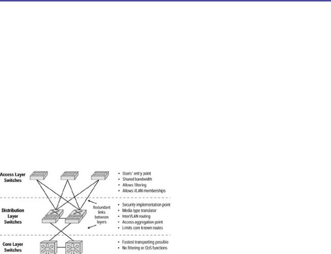
∙Access layer—The first layer, which is the first point of access for the end user interface. This layer passes traffic from the end user interface to the rest of the network. Security at this layer is port−based and provides verification of an authentic MAC address, local device security, and access lists.
∙Distribution layer—The second layer, which serves to combine the traffic of the Access layer, summarize traffic, and combine routes. This layer also processes data traffic and applies security and queuing policies, allowing data traffic to be filtered and providing a guarantee of bandwidth availability for certain traffic.
∙Core layer—Reads headers and forwards traffic as quickly as possible through the network. This is its only function. This layer needs to have high reliability and availability because any losses at this layer can greatly affect the rest of the network.
The Cisco campus hierarchical switching model is depicted in Figure 2.1.
Figure 2.1: The Cisco campus hierarchical switching model.
Access Layer
The Access layer provides some important functionality, such as shared bandwidth, switched bandwidth, Media Access Control (MAC) layer filtering, and microsegmentation. Two goals of this layer are to pass traffic to the network for valid network users and to filter traffic that is passed along.
The Access layer switch connects the physical wire from the end user interface, thereby providing the means to connect to the devices located on the Distribution layer. It provides connections to both the local LAN and remote devices. The Access layer is the entry point to the network. This layer makes security and policy decisions and becomes the logical termination point for virtual private networks (VPNs).
Distribution Layer
The Distribution layer is the demarcation point between the Access and Core layers. This layer terminates network traffic that originates in the Access layer and then summarizes the traffic before passing it along to the highest Core layer. The Distribution layer also provides policy−based network connectivity, such as queuing and data termination.
32