

4.0 Larger engines in the Locost chassis
The standard book chassis was originally designed for small Ford engines. The book refers to engine sizes of 1100cc and 1300cc with the occasional reference to 1600cc. My high stiffness modifications or another equivalent set of modifications to improve stiffness should bring improvements for all engine sizes. For larger engines further changes are advisable.
Tube R is important!
Do not remove tube R to make room for large engines as this tube has a large influence on chassis stiffness. The simplest solution to gaining more width in the engine bay is probably to make two Y shaped structures, one on each side of the engine bay, as follows. Add two tubes running straight back from the outer ends of tubes S and T to about 6 inches from the footwell ends. Add short diagonals from the rear ends of these tubes to the top corners of the footwells. Using two short R tubes is not very good.
The effects of changing tube R on the book chassis are as follows.
Book chassis 1155 ftlbs per degree of twist
Two short R tubes 907 ftlbs per degree of twist
Two Y braces 1215 ftlbs per degree of twist
Slightly bigger engines: 1.6 to 2.0
For slightly larger engines than the book design, about 1.6 to 2.0 litres, tubes TR1 and TR2 begin to become unsatisfactory. This is more to do with these tubes being long and thin, and therefore tending to bend under load, than their actual size. Other tubes also benefit from changes. I would suggest increasing the sizes of some of the tubes as follows.
TR1 and 2
14gauge 1inch diameter or 16gauge 1 inch square minimum
TR3, 4, 5 and 6
16gauge 1 inch square
C, G1, G2 and E
16gauge 1 x 1.5 inches (one and a half inches deep) It may be easier to connect tube G1 and G2 to the ends of tube E
R, J1, J2, N1 and N2
14gauge 1 inch square or 16gauge 1 x 1.5 inches (one and a half inches deep)
Large engines: 2.0 to Rover v8
For bigger engines than 2.0 litres further modifications are required. I suggest the following.
The book chassis stiffness is becoming marginal at this performance level so use my high stiffness modifications or another equivalent set of modifications to improve stiffness.
Replace tube R with two Y braces as described above.
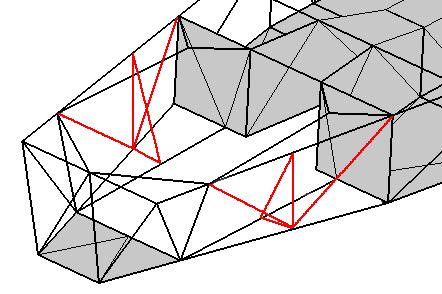
Replace TR1 and TR2 with a new arrangement as follows.
Add a vertical tube on each side of the engine bay from the engine mount positions on tubes F1 and F2 to tubes J1 and J2.
Add two new diagonals on each side of the engine bay from the bottom of the vertical tubes to the tops of FU1 and 2 and the tops of tubes H at the ends of tube Q.
Replace the engine mount plates with tubes connecting F1 to G1 and F2 to G2.
Add tubes from the inner ends of the F to G tubes to the top of the new vertical, F to J, tubes. These tubes are to support the engine mounts.
These changes are shown in the picture below.
Increase the sizes of some of the tubes as follows.
TR3, 4, 5 and 6
16gauge 1 inch square
C, G1, G2 and E
16gauge 1 x 1.5 inches (one and a half inches deep) It may be easier to connect tube G1 and G2 to the ends of tube E.
R, J1, J2, N1 and N2
14gauge 1 inch square or 16gauge 1 x 1.5 inches (one and a half inches deep)
Change the size of K1 and 2 to 14gauge 1 inch square or 16gauge 1 x 1.5 inches (one and a half inches deep)
One important point is that the front lower wishbone is very highly loaded. The book specifies a three quarter inch tube which is only suitable for smaller and lighter engines. I suggest that one inch tubes would be better. This is a simple change to the book design. There are two further changes that will improve the wishbone design but these will involve significant alterations to the design and you may wish to avoid them to keep your build simple.
If you redesign the wishbone then there are two changes that will improve the design. The book design has a distance from the lower hub pivot to the spring mount of 4.3 inches. A smaller distance is better. Some designs have a distance from the lower hub pivot to the spring mount of about two inches. The best shape for the wishbone is a V shape. The tubes of the book wishbone do not form a V shape. The tubes should be positioned on a line connecting the chassis bush centres with the lower hub pivot. In the book the tubes are offset at the outer ends to allow for the width of the lower ball joint mounting plate.