

The effects of frequency and the model
The voltage and current gains of an amplifier are frequency dependent. The
variation of gain with frequency is due to capacitive effects. The source of
such effects is twofold:
(i) coupling capacitors
(ii) internal capacitances of the amplifier.
Let us briefly examine each of these sources in turn.
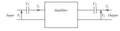
The effects of coupling capacitors placed in the circuit

note the coupling capacitors C1 and C2.
The purpose of these capacitors is to couple, from an a.c. point of view,
the input and output of the amplifier to other stages, without upsetting the
d.c. conditions on the amplifier.
Within the designed frequency range of operation, the coupling capacitors
should behave as short circuits to signals.
Within this range the amplifier can be represented by the simple 'black
box' model as

If we are working outside the designed frequency range of the amplifier,
however, we may have to include the coupling capacitors in the model as
Remember, that a capacitor's reactance falls with increasing frequency. Thus, if a coupling capacitor can be regarded as a short circuit within the designed operating
range, then this assumption will be even more valid at frequencies above this
range. At frequencies below this range, however, the effects of the coupling
capacitors cannot be ignored.
(II) Internal capacitances of the device within the box
There can be many causes of 'internal' capacitance. For example, in the
case of a transistor amplifier there are the interelectrode capacitances of
the transistor itself. The diagram below shows the three interelectrode
capacitances of a transistor.
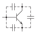
It can be possible to show that two of these capacitance effects can be represented by a single equivalent capacitor Ci. Our black box model can be amended, if required, to include this equivalent input capacitance.

Remember, that the capacitance Ci appears in parallel with the input resistance of the amplifier. If, within the normal frequency range of the amplifier the effects of
Ci can be ignored, then this will be even more true at frequencies below this
range. At higher frequencies, however, the reactance of Ci will fall and its
effects cannot be ignored. It will tend to shunt the input resistance.
Effects of a capacitive load on the amplifier
In the foregoing discussion we have identified the possible causes of reactance
which could limit the frequency performance of our electronic black box.
Imagine, now, that one black box is used to drive another, as shown below
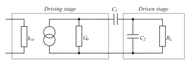
The driving stage is represented in the usual way by an input equivalent circuit,
in this case simply a resistance, and an output equivalent circuit consisting of a
current generator and the output conductance Go. This conductance is due to
the combined effects of the transistor's output conductance, hoe, in parallel with
the collector resistor Rc. The driving stage is coupled by C1 to the driven stage.
Only a modified input equivalent circuit is shown for the output circuit. It
consists of a capacitance C2 in parallel with a resistance RL.
C2 and RL represent the total loading of the second stage upon the first. To
predict the frequency behavior of the circuit, all we need do is to express
the current and voltage gains as a function of frequency. It is usually possible to identify three different frequency ranges in which an amplifier can operate. This will enable us to ignore some, or even all, of the capacitive effects within a particular range.
________________________________________________________________________________________
THE THREE FREQUENCY RANGES OF OPERATION
________________________________________________________________________________________
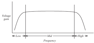
You can see the typical frequency response of an amplifier.
The graph can be seen to consist of three ranges:
(i) a low-frequency range in which the gain increases with increasing
frequency
(ii) a mid-frequency range over which the gain is relatively constant
(iii) a high frequency range over which the gain falls with increasing
frequency.
For simplicity, let's consider the mid-frequency range first.
THE MID-FREQUENCY RANGE
Over this range the coupling capacitors are assumed to be behaving themselves
and may be regarded as having negligible impedance (compared to the
resistances in the circuit). They can, therefore, be ignored in any calculation.
Conversely, the box's internal capacitances, which are low in value, will have a