

The equivalent circuit of the y parameter model
Consider the input equation of the y parameter pair:
![]()
The equation tells us that I1 is equal to:
• a current flowing through a conductance y11 that has a voltage V1
across it
plus • the current generated from a current generator y12V2.
y12 is a reverse trans-conductance representing feedback from output to input.
The input equivalent circuit can be drawn as

Now consider the output equation
![]()
This equation tells us that the output current I2 is equal to the current produced
by a current generator y21V1 plus the current flowing through conductance y22
that has a voltage V2 across it. y21 represents a forward trans-conductance,
often referred to as the mutual conductance.
The output equivalent circuit is now drawn as
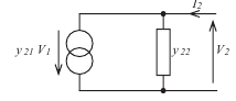
The complete equivalent circuit can be drawn as

The parameter y11 represents the input conductance with the output short
circuit.
The parameter y22 represents the output conductance with the input short
circuit.
________________________________________________________________________________________
The equivalent circuit of the h parameter model
________________________________________________________________________________________
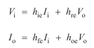
Consider the input equation
![]()
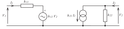
This shows the input voltage to be equal to the sum of
• the voltage across an input resistance h11 that has the input current
I1 flowing through it
and • the voltage h12V2 produced by a voltage generator.
The input equivalent circuit will be as

Now consider the output equation
![]()
This equation tells us that the output current I2 is equal to the sum of a current
produced by the current generator h21I1 and the current due to the voltage V2
across an output conductance h22.
The output equivalent circuit will be as

The complete equivalent circuit will be as
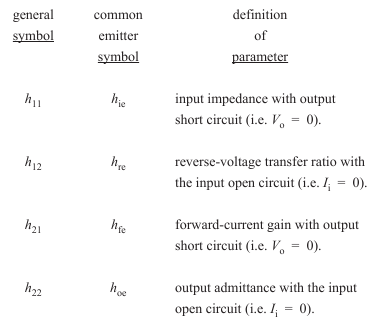
The h parameter model of the common emitter circuit
Consider the equivalent circuit
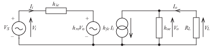
The output is terminated on load RL, which has a value of 1 kΩ. Given the following h parameters, calculate the overall voltage gain from source to load (i.e. VL/VS).
hie = 1000Ω, hre = 2 10–4, hfe = 200, hoe = 10–4 S
Note that in this example VS = Vi and VL = Vo so that VL/VS = Vo/Vi.
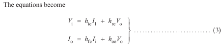
The problem is essentially one of solving the pair of simultaneous equations
The snag is we have four unknowns. But Io can readily be expressed in terms
of Vo and RL.
![]()
Remember that the current Io is flowing into the circuit but, according to the
assumed polarity of Vo, the upper end of RL is shown as being positive.

In other words, the assumed directions of Io and Vo contradict each other. Hence the need for the minus sign. This is a point to watch in all circuits where assumptions
have arbitrarily been made about polarities and current directions.
Thus, Io = –Vo/1000 in our example, which enables a substitution for Io in the
output equation. To save a lot of messy algebra, the numerical values of the h
parameters can also be entered into the output equation.
![]()