

Network analysis
You know that the circuit consists of a source, a load and an interface between them. The source and the load, as a rule, are one port networks. Interface is represented as a two port network. A systems approach is used where we regard to two port network (for example, the amplifier) as a 'black box' having an input and an output. We do not need to know what is inside the box as it is represented by a pair of simultaneous equations which show how the box behaves to the outside world. The advantage of this method is that, having once been given the equations, we need only a rudimentary knowledge of electronics in order to predict the behavior of the box. The treatment given is perfectly general; it could be applied to almost any system that can be represented as a two port network.
Finally, we should note one assumption about the 'black box' approach that we
are about to adopt. This is that the system in the box is assumed to be linear.
There are two important properties of a linear system:
1. That the principle of superposition holds. By this we mean that if an
input signal Vi1 to our system gives an output Vo1 and an input signal Vi2
gives an output Vo2, then an input of (Vi1 + Vi2) will give an output
(Vo1 + Vo2).
2. That frequency conservation is maintained. In other words there are no
frequencies present in the output that were not present in the input.
Please note the following:
(i) Much use is made of the 'ratio method' for determining the current in each
of a pair of parallel resistors:

(ii) Use is also made of the 'method of units' to determine the nature of the
variables in an equation. For example, consider the equation
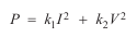
If P is power in watts, then each term on the right hand side must also
represent power in watts. For this to be so, k1 must represent resistance
and k2 conductance.
(iii) We assume that all voltages and currents are r.m.s. values. As is the convention, these are represented by 'V' and 'I' respectively.
The transistor amplifier circuit
A transistor is a three terminal semiconductor device. It can be
represented by the one common symbol shown below.

Note the names of each terminal. Having three terminals means that there are
several ways of connecting the transistor into a circuit, but by far the most
common is the common emitter configuration. In this configuration the base
is used as the input, the collector as the output and the emitter forms a common
terminal between input and output. With this arrangement the transistor acts as
an amplifier, providing both current and voltage amplification. Figure underneath shows a typical common emitter amplifier circuit.
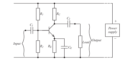
We shall make no attempt to explain the operation of this circuit in this case; for our purposes an understanding is not required. We are going to adopt a 'systems' approach, where the amplifier is merely represented by a 'black box'.
The black box model
The black box representation of our amplifier is shown below

(In point of fact the box could represent any system having a single input and
single output.) Note the convention assumed for the positive direction of
currents and voltages. In particular, observe the directions I1 and I2. It is the
accepted convention to have both currents flowing into the box. Note also that
the subscript notation '1' for input and '2' for output is used.
We have said that in the common emitter amplifier, the base is input, the
collector the output and the emitter is common to both input and output. The
transistor can therefore be pictured connected within the box as shown in the figure below

Thus, the transistor can be represented by a two port (input port and output
port), four terminal (a,b,c,d) box by extending the emitter from input to output.
Note also, in the black box approach, only signals (i.e. input and output
voltages and currents) are shown. No attempt is made to show power supplies
and the like, which are taken for granted.