

Figure 19: Classification of Timing Constraints
A classification of the different types of timing constraints that we discussed in this section is shown in Fig.
Note that a performance constraint can either be delay, deadline, or durational type. The delay or deadline constraints on performance can either be RR or RS type. Similarly, the behaviorial constraints can either be delay, deadline, or durational type. The delay or deadline constraints on behavior of environment can either be RS or SS type.
Modelling Timing Constraints
In this section we describe how the timing constraints identified in Sec. 1.7.3 can be modelled. Modelling time constraints is very important since once a model of the time constraints in a system is constructed, it can serve as a formal specification of the system. Further, if all the timing constraints in a system are modelled accurately, then it may even be used to automatically generate code from it. Besides serving as a specification, modelling time constraints can help to verify and understand a real-time system.
The modelling approach we discuss here is based on Finite State Machines (FSMs). An FSM is a powerful tool which has long been used to model traditional systems. In an FSM, a state is defined in terms of the values assumed by some attributes. For example, the states of an elevator may be denoted in terms of its directions of motion. Here direction is the attribute, based on which the states up, down, and stationery are defined.
In an FSM model, at any point of time a system can be in any one of a (possibly infinite) number of states. A state is represented by a circle. The system changes state due to events that change the values of, or relations among the state variables. A state change is also called a state transition. A transition causing event may either be an interface event that are transmitted between the environment and the computer system or it could also be an internal event that is generated and consumed solely within the system. A transition from one state to another is represented by drawing a directed arc from the source to the destination (see Fig. 20). The event causing a transition is annotated on the arc. We keep our discussions of FSM to the bare minimum since we assume that the reader is familiar with basic FSM modelling of traditional systems.
We use an Extended Finite State Machine (EFSM) to model time constraints. EFSM extends the traditional FSM by incorporating the action of setting a timer and the expiry event of a timer. The notations we use for construction of EFSMs are simple and straightforward. Therefore rather than introducing them formally, we have illustrated them through an example in Fig. 20. The example shown in Fig. 20 describes that if an event el occurs when the current state of the system is si, then an action will be taken by setting a timer to expire in the next 20 milli seconds and the system transits to state s2.
Figure
20: Conventions Used in Drawing an EFSM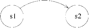
We have already discussed that events can be considered to be of two types: stimulus events and response events. We had also discussed different types of timing constraints in Section 1.7.3. Now we explain how these constraints can be modelled by using EFSMs.
Stimulus-Stimulus (SS) constraints: Let us consider the example of an SS type of deadline constraint we had discussed in Section 1.7.3: Once the first digit has been dialled on the telephone handset, the next digit must be dialled within the next 5 milli seconds. This has been modelled in Fig. 21. In Fig. 21 observe that as soon as the first digit is dialled, the system enters the “Await Second Digit” state and the timer is set to 20 milli seconds. If the next digit does not appear within 20 milli seconds, then the timer alarm expires and the system enters the “Await Caller On-hook” state and a beeping sound is produced. If the second digit occurs before 20 milli seconds, then the system transits to the “Await Next Digit” state.
Figure
21: Model of an SS Type of Deadline Constraint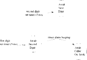
Response^Stimulus(RS) constraint: In Sec. 1.7.3, we had considered the following example of an RS type of deadline constraint: Once the dial tone appears, the first digit must be dialed within 30 seconds, otherwise the system enters an idle state and an idle tone is produced.
The EFSM model for this constraint is shown in Fig. 22. In Fig. 22, as soon as dial tone appears, a timer is set to expire in 30 seconds and the system transits to the “Await First Digit” state. If the timer expires before the first digit arrives, then the system transits to an idle state where an idle tone is produced. Otherwise, if the digit appears first, then the system transits to the ” Await Second Digit” state.
Stimulus^Response(SR): In Sec. 1.7.3, we had considered the following example of an SR type of deadline constraint: Once the receiver of the hand set is lifted, the dial tone must be produced by the system within 20 seconds, otherwise a beeping sound is produced until the handset is replaced.
The EFSM model for this constraint is shown in Fig. 23. As soon as the handset is lifted, a timer is set to expire after 2 sec and the system transits to “Await Dial Tone” state. If the dial tone appears first, then the system transits
Figure
22: Model of an RS Type of Deadline Constraint to “Await First
Digit” state. Otherwise, it transits to “Await Receiver
On-hook” state.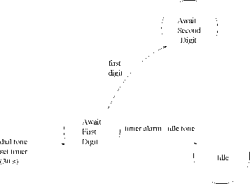
Figure
23: Model of an SR Type of Deadline Constraint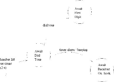
Response^Response(RR): In Sec. 1.7.3, we had considered the following example of an RR type of constraint: Once the ring tone is given to the callee, the corresponding ring back tone must be given to the caller within two seconds, otherwise the call is terminated.
The EFSM model for this constraint is shown in Fig. 24. In Fig. 24, as soon as the ring tone is produced, the system transits to await ring-back tone state and a timer is set to expire in 2 Secs. If the ring-back tone appears first, the system transits to “Await First Digit” state, else it enters “Await Receiver On-hook” state, and the call is terminated.
Delay Constraint: A delay constraint between two events is one where after an event occurs, a minimum time must elapse before the other event can occur. We had considered the following example of delay constraint in Sec. 1.7.3: After a digit is dialed, the next digit should be dialed no sooner than 10 milli seconds. The EFSM model for it is shown in Fig. 25. In Fig. 25, if the next digit appears before the alarm, then the beeping sound is produced and the system transits to “await caller on-hook” state.
Durational Constraint: In case of a durational constraint, an event is required to occur for a specific duration. The example of a durational constraint we had considered in Sec. 1.7.3 is the following: If you press the button of the handset for less than 15 seconds it connects to the local operator. If you press the button for any duration lasting between 15 to 30 seconds, it connects to the international operator. If you keep the button pressed for more than 30 seconds, then on releasing it would produce the dial
Figure
24: Model of an RR Type of Deadline Constraint
Figure
25: Model of an SS Type of Delay Constraint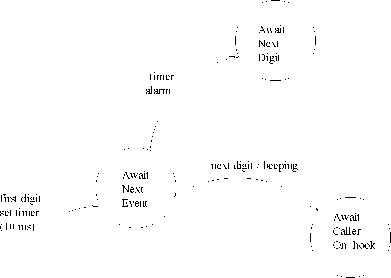
The EFSM model for this example is shown in Fig. 26. Note that we have introduced two intermediate states “Await Event ” and “Await Event 2” to model a durational constraint.
SUMMARY
The main aim of this Chapter was to introduce you to some very basic concepts and terminologies associated with real-time systems that would be used throughout this book.
A system is said to be real-time when quantitative expressions of time are necessary to describe the behavior of the system.
A real-time task is one that is associated with some time constraints.
A real-time task is classified into either hard, firm, or soft real-time type depending on the consequences of a task failing to meet its timing constraints.
A safety-critical system is one which does not have a fail-safe state and any failure of the system can cause severe damage. Many hard real-time systems are safety-critical in nature.
The typical characteristic features of a hard real-time system include embedded, feedback and distributed structure, and safety-criticality. It is possible though that some hard real-time systems may not have these features.
Figure
26: A Model of a Durational Constraint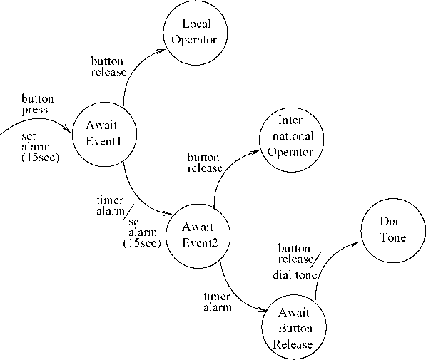
There are two main categories of time constraints in embedded hard real-time systems: performance constraints and behavioral constraints. Performance constraints are timing constraints imposed on the response of the controlling computer system, whereas behaviorial constraints are timing constraints imposed on the behavior of the environment. The performance constraints may not be guaranteed if the behaviorial constraints are not satisfied.
We discussed how to model the performance and behaviorial types of constraints using an Extended Finite State Machine (EFSM) that extends the traditional FSM with the concepts of setting a timer and the corresponding generation of a timer alarm event. Such a model in addition to serve as a specification technique, can also help in verufucation and automatic code generation.
EXERCISES
State whether you consider the following statements to be TRUE or FALSE. Justify your answer in each case.
A hard real-time application is made up of only hard real-time tasks.
Every safety-critical real-time system has a fail-safe state.
A deadline constraint between two stimuli can be considered to be a behaviorial constraint on the environment of the system.
Hardware fault-tolerance techniques can easily be adapted to provide software fault-tolerance.
A good algorithm for scheduling hard real-time tasks must try to complete each task in the shortest time possible.
All hard real-time systems are safety-critical in nature.
Performance constraints on a real-time system ensure that the environment of the system is well-behaved.
Soft real-time tasks are those which do not have any time bounds associated with them.
Minimization of average task response times is the objective of any good hard real-time task-scheduling algorithm.
(j) It should be the goal of any good real-time operating system to complete every hard real-time task as ahead of its deadline as possible.
What do you understand by the term “real-time”? How is the concept of real-time different from the traditional notion of time? Explain your answer using a suitable example.
What does the term “real” in a real-time system signify? Explain what do you mean by a real-time system.
Using a block diagram show the important hardware components of a real-time system and their interactions. Explain the roles of the different components.
In a real-time system, raw sensor signals need to be preprocessed before they can be used by a computer. Why is it necessary to preprocess the raw sensor signals before they can be used by a computer? Explain the different types of preprocessing that are normally carried out on sensor signals to make them suitable to be used directly by a computer.
Identify the key differences between hard real-time, soft real-time, and firm real-time systems. Give at least one example of real-time tasks corresponding to these three categories. Identify the timing constraints in your tasks and justify why the tasks should be categorized into the categories you have indicated.
Explain the key differences between the characteristics of a soft real-time task such as web browsing and a non-real-time task such as e-mail delivery.
Give an example of a soft real-time task and a non-real-time task. Explain the key difference between the characteristics of these two types of tasks.
Name any two important sensor devices and two actuator devices used in real-time applications and explain the physical principles behind their working.
Draw a schematic model showing the important components of a typical hard real-time system. Explain the working of the output interface using a suitable schematic digram. Explain using a suitable circuit diagram how digital to analog (DAC) conversion can be achieved in an output interface.
Draw a schematic model showing the important components of a typical hard real-time system. Explain the working of the input interface using a suitable schematic digram. Explain using a suitable circuit diagram how analog to digital (ADC) conversion is achieved in an input interface.
In a hard real-time system, is it necessary that every task in the system be of hard real-time type? Explain your answer using a suitable example.
In the context of providing system-level fault-tolerance, why are hardware failures more predictable and easier to handle compared to software failures? Explain the N-version scheme to provide software fault-tolerance. What are the shortcomings of this scheme? How does the recovery block technique attempt to overcome it? Does it succeed? Explain your answer.
Explain the checkpointing and rollback recovery scheme to provide fault-tolerant real-time computing. Explain the types of faults it can help tolerate and the faults it can not tolerate. Explain the situations in which this technique is useful.
Answer the following questions concerning fault-tolerance of real-time systems.
Explain why hardware fault-tolerance is easier to achieve compared to software fault-tolerance.
Explain the main techniques available to achieve hardware fault tolerance.
What are the main techniques available to achieve software fault-tolerance? What are the shortcomings of these techniques?
Briefly explain how hardware failures (e.g. processor failures) can be tolerated in safety-critical hard real-time applications. Consider the fact that hard real-time tasks have stringent deadlines which must be met under all circumstances.
What do you understand by the “fail-safe” state of a system? Safety-critical real-time systems do not have a fail-safe state. What is the implication of this?
Explain why safety and reliability are not independent issues in safety-critical hard real-time systems. Explain the basic techniques you would adopt to develop a software product that is required to be highly reliable.
Is it possible to have an extremely safe but unreliable system? If your answer is affirmative, then give an example of such a system. If you answer in the negative, then justify why it is not possible for such a system to exist.
What is a safety-critical system? Give a few practical examples safety-critical hard real-time systems. Are all hard real-time systems safety-critical? If not, give at least one example of a hard real-time system that is not safety-critical.
Explain with the help of a schematic diagram how the recovery block scheme can be used to achieve fault- tolerance of real-time tasks. What are the shortcomings of this scheme? Explain situations where it can be satisfactorily be used and situations where it can not be used.
Identify and represent the timing constraints in the following air-defense system by means of an extended state machine diagram. Classify each constraint into either performance or behaviorial constraint.
Every incoming missile must be detected within 0.2 Seconds of its entering the radar coverage area. The intercept missile should be engaged within 5 Seconds of detection of the target missile. The intercept missile should be fired after 0.1 Seconds of its engagement but no later than 1 Sec.
Represent a wash-machine having the following specification by means of an extended state machine diagram. The wash-machine waits for the start switch to be pressed. After the user presses the start switch, the machine fills the wash tub with either hot or cold water depending upon the setting of the HotWash switch. The water filling continues until the high level is sensed. The machine starts the agitation motor and continues agitating the wash tub until either the preset timer expires or the user presses the stop switch. After the agitation stops, the machine waits for the user to press the start Drying switch. After the user presses the startDrying switch, the machine starts the hot air blower and continues blowing hot air into the drying chamber until either the user presses the stop switch or the preset timer expires.
In a real-time system what is the difference between a performance constraint and a behaviorial constraint? Give practical examples of each type of constraint.
Represent the timing constraints in a collision avoidance task in an air surveillance system as an extended finite state machine (EFSM) diagram. The collision avoidance task consists of the following activities.
The first subtask named radar signal processor processes the radar signal on a signal processor to generate the track record in terms of the target’s location and velocity within 100 mSec of receipt of the signal.
The track record is transmitted to the data processor within 1 mSec after the track record is determined.
A subtask on the data processor correlates the received track record with the track records of other targets that come close to detect potential collision that might occur within the next 500 mSec.
If a collision is anticipated, then the corrective action is determined within 10 mSec by another subtask running on the data processor.
The corrective action is transmitted to the track correction task within 25 mSec.
Consider the following (partial) specification of a real-time system:
The velocity of a space-craft must be sampled by a computer on-board the space-craft at least once every second (the sampling event is denoted by S). After sampling the velocity, the current position is computed (denoted by event C) within 100msec, parallelly the expected position of the space-craft is retrieved from the database within 200msec (denoted by event R). Using these data, the deviation from the normal course of the space-craft must be determined within 100 msec (denoted by event D) and corrective velocity adjustments must be carried out before a new velocity value is sampled in (the velocity adjustment event is denoted by A). Calculated positions must be transmitted to the earth station at least once every minute (position transmission event is denoted by the event T).
Identify the different timing constraints in the system. Classify these into either performance or behaviorial constraints. Construct an EFSM to model the system.
Construct the EFSM model of a telephone system whose (partial) behavior is described below:
After lifting the receiver handset, the dial tone should appear within 20 seconds. If a dial tone can not be given within 20 seconds, then an idle tone is produced. After the dial tone appears, the first digit should to be dialled within 10 seconds and the subsequent five digits within 5 seconds of each other. If the dialling of
any of the digits is delayed, then an idle tone is produced. The idle tone continues until the receiver handset
is replaced.
What are the different types of timing constraints that can occur in a system. Give examples of each.
References
B. Dasarathy. Timing constraints of real-time systems: Constructs for expressing them, methods for validating
them. IEEE Transactions on Software Engineering, Vol. ll(No. l):80-86, January 1985.
Steve Heath. Embedded Systems Design. Elsevier, 2003.
Brian Santo. Embedded battle royale. IEEE Spectrum, pages 36-42, December 2001.