

Figure 2: a Bus Architecture
There is a single shared channel for which the transmitting nodes contend. The most commonly used protocol for access control in traditional bus networks is the Carrier Sense Multiple Access with Collision Detection (CSMA/CD)
. In bus networks, when two or more nodes transmit packets simultaneously, they overlap in time and the resulting signal gets garbled. Such an event is called a collision. A collision entails retransmission of the corrupted data.
In CSMA/CD networks, any node can at any time sense the channel to determine whether the channel is idle. A node transmits a packet only if it senses the channel to be idle. But, this does not guarantee that there will be no collisions. Several nodes might sense the channel to be idle at the same time instant and start transmitting simultaneously, resulting in a collision. The transmitting nodes can also detect a collision when it occurs. Therefore while transmitting a packet, a node would check for a collision and would immediately stop transmitting, if it detects one. Large propagation delays increase the probability of collisions.
Ethernet is a LAN standard based on CSMA/CD access control. Due to its ubiquity, high speed, simplicity and low cost, Ethernet has over the years emerged as one of the most preferred LAN protocol. It is therefore not surprising that many attempts have been made in the past to design protocols based on Ethernet to support realtime communication. However, the logical ring architecture possesses significant advantages over Ethernet due to its inherent deterministic access arbitration mechanism in contrast to the collision based mechanism of Ethernet. For example, in Ethernet the delay in message transmission increases as the traffic increases. Under high traffic situations, the throughput and maximum delay almost become unacceptable.
Ring-Based Architectures: A ring-based architecture has schematically been shown in Fig. 3. In Fig. 3, an multistation access unit (MSAU) is a hub or concentrator that connects a group of computers (”nodes” in network terminology) to a Token Ring local area network. In a ring-based architecture, the nodes are arranged in a ring and the nodes transmit in turn usually for certain predetermined periods of time. Therefore, the transmission delays are predictable and can be made sufficiently small as per requirement. Therefore, as already mentioned earlier, ring-based architectures are often preferred in real-time applications.
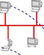
However, the ring architecture suffers from a few important problems. First, any break in the ring can bring the whole network down. This makes reliability of ring networks a major concern. Further, ring is a poor fit to the linear topology normally found in most assembly lines and other applications. This made researchers to look for an alternative technology which can have the advantage of both bus and ring architecture. This led to the development of the token bus architecture. A token bus architecture is a bus based architecture, where the stations on the bus are logically arranged in a ring with each station knowing the address of the station to its ”left” and ” right” (see Fig. 4).
When the logical ring is initialized, the highest numbered station gets a chance to initiate its transmission. After completing transmission for a predetermined time, the station passes the frame transmission permission to its immediate (left or right as per the convention adopted) neighbor by sending a special control frame called a token.
Legend:
MSAU:
Multistation Access Unit
Figure
3: A Ring Architecture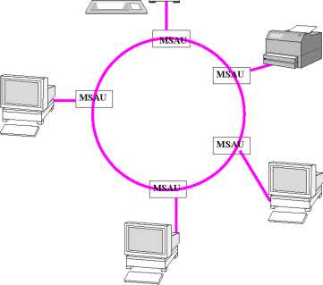
 The
token propagates around the logical ring. At any time only the token
holder is permitted to transmit frames. Since only one station at a
time holds the token in a ring network, collisions can not occur. An
important point to realize is that the physical order in which the
stations are connected to the cable is not important. This is because
the cable is inherently a broadcast medium, each station receives
every frame transmitted, discarding those that are not addressed to
it. When a station passes the token, it transmits a special token
frame, specifically addressed to its logical neighbor in the ring,
irrespective of where that station is physically located on the
cable. It is also worth noting that many stations on the network may
not be not in the ring (for e.g. stations 11, 15 in the Fig. 4). The
MAC protocol also provides for adding stations to, and removing
stations from the logical ring.
The
token propagates around the logical ring. At any time only the token
holder is permitted to transmit frames. Since only one station at a
time holds the token in a ring network, collisions can not occur. An
important point to realize is that the physical order in which the
stations are connected to the cable is not important. This is because
the cable is inherently a broadcast medium, each station receives
every frame transmitted, discarding those that are not addressed to
it. When a station passes the token, it transmits a special token
frame, specifically addressed to its logical neighbor in the ring,
irrespective of where that station is physically located on the
cable. It is also worth noting that many stations on the network may
not be not in the ring (for e.g. stations 11, 15 in the Fig. 4). The
MAC protocol also provides for adding stations to, and removing
stations from the logical ring.
Logical
Ring
Node not in the ring