

Applications of Real-Time Systems
Real-time systems have of late, found applications in wide ranging areas. In the following, we list some of the prominent areas of application of real-time systems and in each identified case, we discuss a few example applications in some detail. As we can imagine, the list would become very vast if we try to exhaustively list all areas of applications of real-time systems. We have therefore restricted our list to only a handful of areas, and out of these we have explained only a few selected applications to conserve space. We have pointed out the quantitative notions
of time used in the discussed applications. The examples we present are important to our subsequent discussions and would be referred to in the later Chapters whenever required.
Industrial Applications: Industrial applications constitute a major usage area of real-time systems. A few examples of industrial applications of real-time systems are: process control systems, industrial automation systems, SCADA applications, test and measurement equipments, and robotic equipments.
Example 1: Chemical Plant Control
Chemical plant control systems are essentially a type of process control application. In an automated chemical plant, a real-time computer periodically monitors plant conditions. The plant conditions are determined based on current readings of pressure, temperature, and chemical concentration of the reaction chamber. These parameters are sampled periodically. Based on the values sampled at any time, the automation system decides on the corrective actions necessary at that instant to maintain the chemical reaction at a certain rate. Each time the plant conditions are sampled, the automation system should decide on the exact instantaneous corrective actions required such as changing the pressure, temperature, or chemical concentration and carry out these actions within certain predefined time bounds. Typically, the time bounds in such a chemical plant control application range from a few micro seconds to several milli seconds.
Example 2: Automated Car Assembly Plant
An automated car assembly plant is an example of a plant automation system. In an automated car assembly plant, the work product (partially assembled car) moves on a conveyor belt (see Fig. 1). Alongside the conveyor belt, several workstations are placed. Each workstation performs some specific work on the work product such as fitting engine, fitting door, fitting wheel, and spray painting the car, etc. as it moves on the conveyor belt. An empty chassis is introduced near the first workstation on the conveyor belt. A fully assembled car comes out after the work product goes past all the workstations. At each workstation, a sensor senses the arrival of the next partially assembled product. As soon as the partially assembled product is sensed, the workstation begins to perform its work on the work product. The time constraint imposed on the workstation computer is that the workstation must complete its work before the work product moves away to the next workstation. The time bounds involved here are typically of the order of a few hundreds of milli seconds.
chassis
finished
car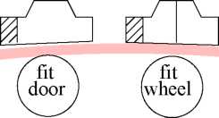

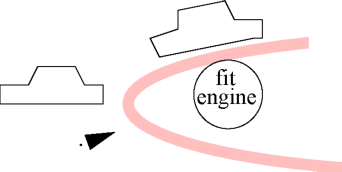
Conveyor Belt
Figure 1: Schematic Representation of An Automated Car Assembly Plant
Example 3: Supervisory Control And Data Aequisition(SCADA )
SCADA are a category of distributed control systems being used in many industries. A SCADA system helps monitor and control a large number of distributed events of interest. In SCADA systems, sensors are scattered at various geographic locations to collect raw data (called events of interest). These data are then processed and stored in a real-time database. The database models (or reflects) the current state of the environment. The database is updated frequently to make it a realistic model of the uptodate state of the environment. An example of a SCADA application is an Energy Management System(EMS). An EMS helps to carry out load balancing in an electrical energy distribution network. The EMS senses the energy consumption at the distribution points and computes the load across different phases of power supply. It also helps dynamically balance
the load. Another example of a SCADA system is a system that monitors and controls traffic in a computer network. Depending on the sensed load in different segments of the network, the SCADA system makes the router change its traffic routing policy dynamically. The time constraint in such a SCADA application is that the sensors must sense the system state at regular intervals (say every few milli seconds) and the same must be processed before the next state is sensed.
Medical: A few examples of medical applications of real-time systems are: robots, MRI scanners, radiation therapy equipments, bedside monitors, and computerized axial tomography (CAT).
Example 4: Robot Used in Recovery of Displaced Radioactive Material
Robots have become very popular nowadays and are being used in a wide variety of medical applications. An application that we discuss here is a robot used in retrieving displaced radioactive materials. Radioactive materials such as Cobalt and Radium are used for treatment of cancer. At times during treatment, the radioactive Cobalt (or Radium) gets dislocated and falls down. Since human beings can not come near a radioactive material, a robot is used to restore the radioactive material to its proper position. The robot walks into the room containing the radioactive material, picks it up, and restores it to its proper position. The robot has to sense its environment frequently and based on this information, plan its path. The real-time constraint on the path planning task of the robot is that unless it plans the path fast enough after an obstacle is detected, it may collide with it. The time constraints involved here are of the order of a few milli seconds.
Peripheral equipments: A few examples of peripheral equipments that contain embedded real-time systems are: laser printers, digital copiers, fax machines, digital cameras, and scanners.
Example Б: Laser Printer
Most laser printers have powerful microprocessors embedded in them to control different activities associated with printing. The important activities that a microprocessor embedded in a laser printer performs include the following: getting data from the communication port(s), typesetting fonts, sensing paper jams, noticing when the printer runs out of paper, sensing when the user presses a button on the control panel, and displaying various messages to the user. The most complex activity that the microprocessor performs is driving the laser engine. The basic command that a laser engine supports is to put a black dot on the paper. However, the laser engine has no idea about the exact shapes of different fonts, font sizes, italic, underlining, boldface, etc. that it may be asked to print. The embedded microprocessor receives print commands on its input port and determines how the dots can be composed to achieve the desired document and manages printing the exact shapes through a series of dot commands issued to the laser engine. The time constraints involved here are of the order of a few milli seconds.
Automotive and Transportation: A few examples of automotive and transportation applications of real-time systems are: automotive engine control systems, road traffic signal control, air-traffic control, high-speed train control, car navigation systems, and MPFI engine control systems.
Example 6: Multi-Point Fuel Injection (MPFI) System
An MPFI system is an automotive engine control system. A conceptual diagram of a car embedding an MPFI system is shown in Fig. 2. An MPFI is a real-time system that controls the rate of fuel injection and allows the engine to operate at its optimal efficiency. In older models of cars, a mechanical device called the carburettor was used to control the fuel injection rate to the engine. It was the responsibility of the carburettor to vary the fuel injection rate depending on the current speed of the vehicle and the desired acceleration. Careful experiments have suggested that for optimal energy output, the required fuel injection rate is highly nonlinear with respect to the vehicle speed and acceleration. Also, experimental results show that the precise fuel injection through multiple points is more effective than single point injection. In MPFI engines, the precise fuel injection rate at each injection point is determined by a computer. An MPFI system injects fuel into individual cylinders resulting in better ‘power balance’ among the cylinders as well as higher output from each one along with faster throttle response. The processor primarily controls the ignition timing and the quantity of fuel to be injected. The latter is achieved by controlling the duration for which the injector valve is open — popularly known as
pulse width. The actions of the processor are determined by the data gleaned from sensors located all over the engine. These sensors constantly monitor the ambient temperature, the engine coolant temperature, exhaust temperature, emission gas contents, engine rpm (speed), vehicle road speed, crankshaft position, camshaft position, etc. An MPFI engine with even an 8-bit computer does a much better job of determining an accurate fuel injection rate for given values of speed and acceleration compared to a carburettor-based system. An MPFI system not only makes a vehicle more fuel efficient, it also minimizes pollution by reducing partial combustion.
Multi
Point Fuel Injection (MPFI) System
Figure
2: A Real-Time System Embedded in An MPFI Car
Computer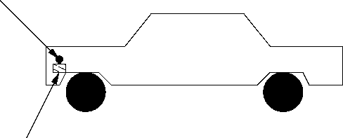
Telecommunication Applications: A few example uses of real-time systems in telecommunication applications are: cellular systems, video conferencing, and cable modems.
Example 7: A Cellular System
Cellular systems have become a very popular means of mobile communication. A cellular system usually maps a city into cells. In each cell, a base station monitors the mobile handsets present in the cell. Besides, the base station performs several tasks such as locating a user, sending and receiving control messages to a handset, keeping track of call details for billing purposes, and hand-off of calls as the mobile moves. Call hand-off is required when a mobile moves away from a base station. As a mobile moves away, its received signal strength (RSS) falls at the base station. The base station monitors this and as soon as the RSS falls below a certain threshold value, it hands-off the details of the on-going call of the mobile to the base station of the cell to which the mobile has moved. The hand-off must be completed within a sufficiently small predefined time interval, so that the user does not feel any temporary disruption of service during the hand-off. Typically call hand-off is required to be achieved within a few milliseconds.
Aerospace: A few important use of real-time systems in aerospace applications are: avionics, flight simulation, airline cabin management systems, satellite tracking systems, and computer on-board an aircraft.
Example 8: Computer On-board an Aircraft
In many modern aircrafts, the pilot can select an “auto pilot” option. As soon as the pilot switches to the “auto pilot” mode, an on-board computer takes over all controls of the aircraft including navigation, take-off, and landing of the aircraft. In the “auto pilot” mode, the computer periodically samples velocity and acceleration of the aircraft. From the sampled data, the on-board computer computes X, Y, and Z co-ordinates of the current aircraft position and compares them with the pre-specified track data. Before the next sample values are obtained, it computes the deviation from the specified track values and takes any corrective actions that may be necessary. In this case, the sampling of the various parameters, and their processing need to be completed within a few micro seconds.
Internet and Multimedia Applications: Important use of real-time systems in multimedia and Internet applications include: video conferencing and multimedia multicast, Internet routers and switches.
Example 9: Video Conferencing
In a video conferencing application, video and audio signals are generated by cameras and microphones respectively. The data are sampled at a certain prespecified frame rate. These are then compressed and sent
as packets to the receiver over a network. At the receiver-end, packets are ordered, decompressed, and then played. The time constraint at the receiver-end is that the receiver must process and play the received frames at a predetermined constant rate. Thus if thirty frames are to be shown every minute, once a frame play-out is complete, the next frame must be played within two seconds.
Consumer Electronics: Consumer electronics area abounds numerous applications of real-time systems. A few sample applications of real-time systems in consumer electronics are: set-top boxes, audio equipment, Internet telephony, microwave ovens, intelligent washing machines, home security systems, air conditioning and refrigeration, toys, and cell phones.
Example 10: Cell Phones
Cell phones are possibly the fastest growing segment of consumer electronics. A cell phone at any point of time carries out a number of tasks simultaneously. These include: converting input voice to digital signals by deploying digital signal processing (DSP) techniques, converting electrical signals generated by the microphone to output voice signals, and sampling incoming base station signals in the control channel. A cell phone responds to the communications received from the base station within certain specified time bounds. For example, a base station might command a cell phone to switch the on-going communication to a specific frequency. The cell phone must comply to such commands from the base station within a few milli seconds.
Defense Applications: Typical defense applications of real-time systems include: missile guidance systems, antimissile systems, satellite-based surveillance systems.
Example 11: Missile Guidance System
A guided missile is one that is capable of sensing the target and homes onto it. Homing becomes easy when the target emits either electrical or thermal radiation. In a missile guidance system, missile guidance is achieved by a computer mounted on the missile. The mounted computer computes the deviation from the required trajectory and effects track changes of the missile to guide it onto the target. The time constraint on the computer-based guidance system is that the sensing and the track correction tasks must be activated frequently enough to keep the missile from diverging from the target. The target sensing and track correction tasks are typically required to be completed within a few hundreds of microseconds or even lesser time depending on the speed of the missile and the type of the target.
Miscellaneous Applications: Besides the areas of applications already discussed, real-time systems have found numerous other applications in our every day life. An example of such an application is a railway reservation system.
Example 12: Railway Reservation System
In a railway reservation system, a central repository maintains the up-to-date data on booking status of various trains. Ticket booking counters are distributed across different geographic locations. Customers queue up at different booking counters and submit their reservation requests. After a reservation request is made at a counter, it normally takes only a few seconds for the system to confirm the reservation and print the ticket. A real-time constraint in this application is that once a request is made to the computer, it must print the ticket or display the seat unavailability message before the average human response time (about 20 seconds) expires, so that the customers do not notice any delay and get a feeling of having obtained instant results. However, as we discuss a little later (in Sec. 1.6), this application is an example of a category of applications that is in some aspects different from the other discussed applications. For example, even if the results are produced just after 20 Secs, nothing untoward is going to happen — this may not be the case with the other discussed applications.
A Basic Model of a Real-Time System
We have already pointed out that this book confines itself to the software issues in real-time systems. However, in order to be able to see the software issues in a proper perspective, we need to have a basic conceptual understanding of the underlying hardware. We therefore in this section try to develop a broad understanding of high level issues of the underlying hardware in a real-time system. For a more detailed study of the underlying hardware issues, we refer the reader to [2]. Fig. 3 shows a simple model of a real-time system in terms of its important functional blocks. Unless otherwise mentioned, all our subsequent discussions would implicitly assume such a model. Observe that in Fig. 3, the sensors are interfaced with the input conditioning block, which in turn is connected to the input interface. The output interface, output conditioning, and the actuator are interfaced in a complementary manner. In the following, we briefly describe the roles of the different functional blocks of a real-time system:
operators
Figure
3: A Model of a Real-Time System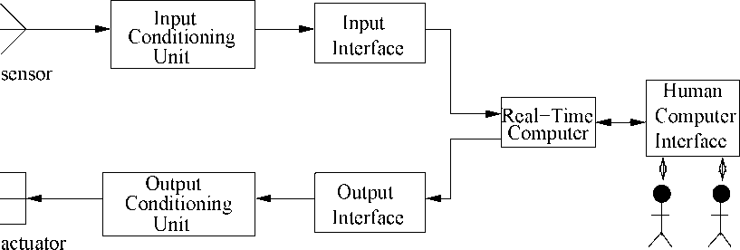
Sensor: A sensor converts some physical characteristic of its environment into electrical signals. An example of a sensor is a photo-voltaic cell which converts light energy into electrical energy. A wide variety of temperature and pressure sensors are also used. A temperature sensor typically operates based on the principle of a thermocouple. Temperature sensors based on many other physical principles also exist. For example, one type of temperature sensor employs the principle of variation of electrical resistance with temperature (called a varistor). A pressure sensor typically operates based on the piezoelectricity principle. Pressure sensors based on other physical principles also exist.
Actuator: An actuator is any device that takes its inputs from the output interface of a computer and converts these electrical signals into some physical actions on its environment. The physical actions may be in the form of motion, change of thermal, electrical, pneumatic, or physical characteristics of some objects. A popular actuator is a motor. Heaters are also very commonly used. Besides, several hydraulic and pneumatic actuators are also popular.
Signal Conditioning Units: The electrical signals produced by a computer can rarely be used to directly drive an actuator. The computer signals usually need conditioning before they can be used by the actuator. This is termed output conditioning. Similarly, input conditioning is required to be carried out on sensor signals before they can be accepted by the computer. For example, analog signals generated by a photo-voltaic cell are normally in the milli volts range and need to be conditioned before they can be processed by a computer. The following are some important types of conditioning carried out on raw signals generated by sensors and digital signals generated by computers:
Voltage Amplification: Voltage amplification is normally required to be carried out to match the full scale sensor voltage output with the full scale voltage input to the interface of a computer. For example, a sensor might produce voltage in the milli volts range, whereas the input interface of a computer may require the input signal level to be of the order of a volt.
Voltage Level Shifting: Voltage level shifting is often required to align the voltage level generated by a sensor with that acceptable to the computer. For example, a sensor may produce voltage in the range -0.5 to +0.5 volt, whereas the input interface of the computer may accept voltage only in the range of 0 to 1 volt. In this case, the sensor voltage must undergo level shifting before it can be used by the computer.
Frequency Range Shifting and Filtering: Frequency range shifting is often used to reduce the noise components in a signal. Many types of noise occur in narrow bands and the signal must be shifted from the noise bands so that noise can be filtered out.
Signal Mode Conversion: A type of signal mode conversion that is frequently carried out during signal conditioning involves changing direct current into alternating current and vice-versa. Another type signal mode conversion that is frequently used is conversion of analog signals to a constant amplitude pulse train such that the pulse rate or pulse width is proportional to the voltage level. Conversion of analog signals to a pulse train is often necessary for input to systems such as transformer coupled circuits that do not pass direct current.
Figure
4: An Output Interface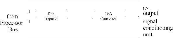
Interface Unit: Normally commands from the CPU are delivered to the actuator through an output interface. An output interface converts the stored voltage into analog form and then outputs this to the actuator circuitry. This of course would require the value generated to be written on a register (see Fig. 4). In an output interface, in order to produce an analog output, the CPU selects a data register of the output interface and writes the necessary data to it. The two main functional blocks of an output interface are shown in Fig. 4. The interface takes care of the buffering and the handshake control aspects. Analog to digital conversion is frequently deployed in an input interface. Similarly, digital to analog conversion is frequently used in an output interface.
In the following, we discuss the important steps of analog to digital signal conversion (ADC).
Figure
5: Continuous Analog Voltage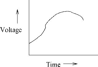
Analog to Digital Conversion:
Digital computers can not process analog signals. Therefore, analog signals need to be converted to digital form. Analog signals can be converted to digital form using a circuitry whose block diagram is shown in Fig. 7. Using the block diagram shown in Fig. 7, analog signals are normally converted to digital form through the following two main
Sample the analog signal (shown in Fig. 5) at regular intervals. This sampling can be done by a capacitor circuitry that stores the voltage levels. The stored voltage level can be discretized. After sampling the analog signal (shown in Fig. 5), a step waveform as shown in Fig. 6 is obtained.