

1. Classifications of electrical systems
classifications of electrical systems:
• communication systems
• computer systems
• control systems
• power systems
• signal-processing systems.
Communication systems are electrical systems that generate, transmit, and distribute information.
Computer systems use electric signals to process information ranging from word processing to mathematical computations. Control systems use electric signals to regulate processes
Power systems generate and distribute electric power.
Signal-processing systems act on electric signals that represent information.
Circuit Theory
In a field as diverse as electrical engineering, you might well ask whether all of its branches have anything in common. The answer is yes—electric circuits. An electric circuit is a mathematical model that approximates the behavior of an actual electrical system.
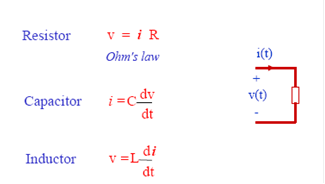
2. Elements of Electric Circuits
Common circuit elements.
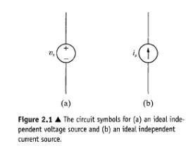
Voltage Sources
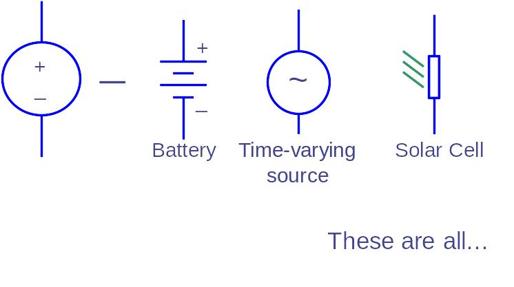
For an ideal voltage source, voltage is independent of current.
 Examples
of voltage sources
Examples
of voltage sources
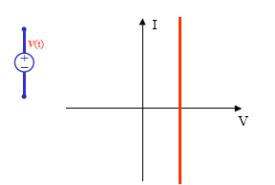
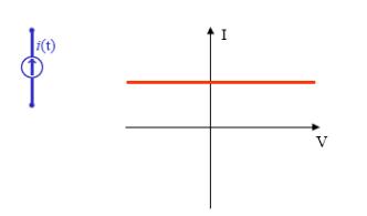
In an ideal current source, current is independent
of voltage
An active element is one that models
a device capable of generating electric energy. Passive elements model
physical devices that cannot generate electric energy. Resistors, inductors,
and capacitors are examples of passive circuit elements.
3. Current sources and voltage sources.
There are five ideal basic circuit elements: voltage sources, current sources, resistors, inductors, and capacitors.
An electrical source is a device that is capable of converting nonelectric energy to electric energy
The important thing to remember about these sources is that they can either deliver or absorb electric power, generally maintaining either voltage or current.
An ideal voltage source is a circuit element that maintains a prescribed voltage across its terminals regardless of the current flowing in those terminals. Similarly, an ideal current source is a circuit element that maintains a prescribed current through its terminals regardless of the voltage across those terminals. These circuit elements do not exist as practical devices—they are idealized models of actual voltage and current sources.
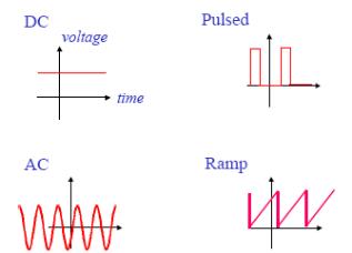
Ideal voltage and current sources can be further described as either independent sources or dependent sources.
4. Thevenin and Norton Equivalents
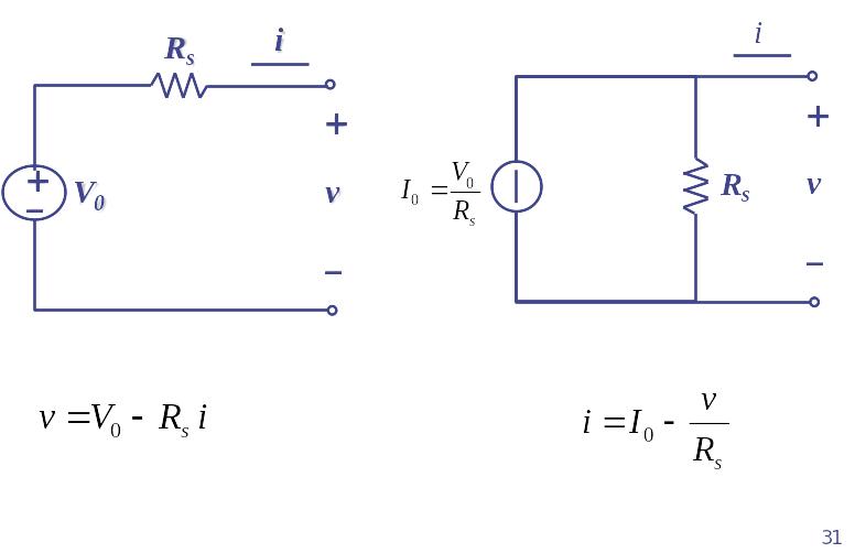
Thevenin and Norton equivalent circuits may be used to represent any circuit made up of linear elements. We can best describe a Thevenin equivalent circuit by reference to Fig. 4.44, which represents any circuit made up of sources (both independent and dependent) and resistors. The letters a and b denote the pair of terminals of interest. Figure 4.44(b) shows the Thevenin equivalent. Thus, a Thevenin equivalent circuit is an independent voltage source VTh in series with a resistor RTh, which replaces an interconnection of sources and resistors. This series combination of VTh and RTh is equivalent to the original circuit in the sense that, if we connect the
same load across the terminals a,b of each circuit, we get the same voltage and current at the terminals of the load. This equivalence holds for all possible values of load resistance.
To represent the original circuit by its Thevenin equivalent, we must be able to determine the Thevenin voltage VJh and the Thevenin resistance Rlh. First, we note that if the load resistance is infinitely large, we have an open-circuit condition. The open-circuit voltage at the terminals a,b in the circuit shown in Fig. 4.44(b) is Vj
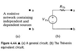
Therefore, to calculate the Thevenin voltage VTh, we simply calculate the open-circuit voltage in the original circuit. Reducing the load resistance to zero gives us a short-circuit condition. If we place a short circuit across the terminals a,b of the Thevenin equivalent
circuit, the short-circuit current directed from a to b is
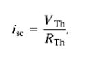
By hypothesis, this short-circuit current must be identical to the short-circuit current that exists in a short circuit placed across the terminals a,b of the original network. From Eq. 4.55,
 (4.56)
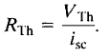
Thus the Thevenin resistance is the ratio of the open-circuit voltage to the short-circuit current.
A Norton equivalent circuit consists of an independent current source in parallel with the Norton equivalent resistance, We can derive it from a Thevenin equivalent circuit simply by making a source transformation. Thus the Norton current equals the short-circuit current at the terminals of interest, and the Norton resistance is identical to the Thevenin resistance.
Fig.2.17 (a) Thevenin equivalent circuit ; (b) Norton equivalent circuit
The
equivalence of these two circuits is a
 special
case of the Thevenin
and Norton Theorem
special
case of the Thevenin
and Norton Theorem
Thevenin's Theorem states that it is possible to simplify any linear circuit, no matter how complex, to an equivalent circuit with just a single voltage source and series resistance connected to a load.
Norton's Theorem states that it is possible to simplify any linear circuit, no matter how complex, to an equivalent circuit with just a single current source and parallel resistance connected to a load. Norton form:
A parallel combination of Norton equivalent current source I0 and Norton equivalent resistance Rs


Thévenin’s Theorem: A resistive circuit can be represented by one voltage source and one resistor: