

Met_OrgSynthesis
.pdfTEXT 8. PHTHALIC ANHYDRIDE (I)
Application. A fluid bed process for the production of high purity phthalic anhydride from naphthalene.
Description. Liquid naphthalene is introduced directly into the reactor at the bottom of the catalyst bed. It is immediately vaporized and dispersed throughout the bed upon contact with hot catalyst and the reaction air which is introduced below the reactor distribution grid. Here in the presence of reaction air and a fluidized vanadium-oxide catalyst, the vaporization and oxidation of naphthalene to phthalic anhydride takes place. Because of the high degree of agitation and mixing within the fluid bed, a uniform temperature is maintained throughout the reaction zone. The bed temperature is controlled within narrow limits in the range of 650° F to 725° F.
Heat from the highly exothermic reaction is removed by cooling tubes located in the catalyst bed and high pressure steam is generated without the need of a secondary heat transfer agent.
Entrained catalyst is removed from the reaction gases in specially constructed ceramic filter elements, and the recovered catalyst is blown back to the reactor. Several filters are provided and one filter vessel at a time is blown back by a stream of air which frees the filter surface of catalyst. Phthalic anhydride product is condensed both as a liquid and a solid from the effluent gases.
The required air to feed ratio in a fluid bed reactor is significantly lower than conventional fixed bed units by a factor of two or three. At this low air ratio, 40 to 60 wt. percent of the crude product can be condensed directly as liquid phthalic anhydride. This fact plus the much lower air rate greatly reduces the load on the solid product condensers with a proportional decrease in plant cost as compared to fixed bed units.
Crude phthalic anhydride is sent to a purification system where simple batch heat treatment and vacuum distillation produce high purity phthalic anhydride. Facilities may be provided to produce a flaked product; however, in modern practice, much is shipped in molten form.
Economics. The development of large capacity fluid bed units has substantially improved the economics of phthalic anhydride production. Plants with capacities of 125-150 MM lb./year of product in a single train are now in operation.
Yields. Yields arc in the order of 98 lbs. phthalic anhydride for 100 lbs. feed.
89
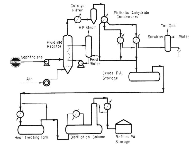
Fig. 10. Phthalic anhydride (I) production scheme
90
TEXT 9. PHTHALIC ANHYDRIDE (II)
Application. A process for the manufacture of phthalic anhydride from naphthalene and air.
Description. Crude phthalic anhydride is produced by the partial oxidation of naphthalene. The main reaction, in the presence of a catalyst, is:
C10H8 + 4.5O2 = C8H4O3 + 2СО2 + 2H2O
The crude phthalic anhydride thus produced is then refined, in the distillation
unit.
Air and naphthalene are fed to the fluidized reactor. Compressed air enters the reactor under the distribution plate. Naphthalene is pumped from the storage tank to spray nozzles in the side of the reactor above the perforated distribution plate.
In the fluidized bed process, the fluidized catalyst particles in the reactor render the vapor mixture in the reactor unexplosive.
The oxidation reaction takes place in the bed of fluidized catalyst. The reaction heat is removed in a cooler consisting of elements immersed in the catalyst. Boiler feedwater is fed to the tubes and is converted to high pressure superheated steam. The reaction temperature is controlled by metering the boiler feedwater.
For startup an in-line air preheater brings the combustion products to a controlled temperature and the -catalyst in the reactor is brought to reaction temperature within a few hours. When normal operation is under way, the fuel to the air preheater is shut off.
A catalyst storage vessel and eductor for loading and unloading the catalyst permit the catalyst to be loaded without shutting down the unit. One complete reactor charge, can be stored in the catalyst storage vessel.
The mixed vapors leaving the reactor pass to a group of filter vessels. By a time-cycle mechanism, one vessel at a time may be blown back by a stream of air, freeing the filter surface of catalyst. The fines are blown back to the dense phase catalyst bed inside the reactor.
Crude phthalic anhydride leaves the filter vessels as vapor which includes nitrogen, oxygen, carbon dioxide, water vapor and byproducts. This stream flows to a condenser where a large portion of the phthalic anhydride is recovered in liquid form. Final recovery of crude product as a solid is in parallel condensers run on a condensing melting cycle. Spent gas containing traces of odoriferous organics is treated with either scrubbing or combustion apparatus for pollution abatement.
Molten crude phthalic is thermally treated prior to vacuum batch distillation. During the first few hours of distillation a forecut is taken to remove light ends.
This forecut returns by gravity to the synthesis unit.
After removal of the light ends the distillation continues. During this time the product is withdrawn from the reflux divider and passed to the pure anhydride receiver where it may be withdrawn as a liquid or it may be flaked.
The residual material left in the main still is treated in a tails still from which an overhead cut is recycled and pitch discharged to waste.
91
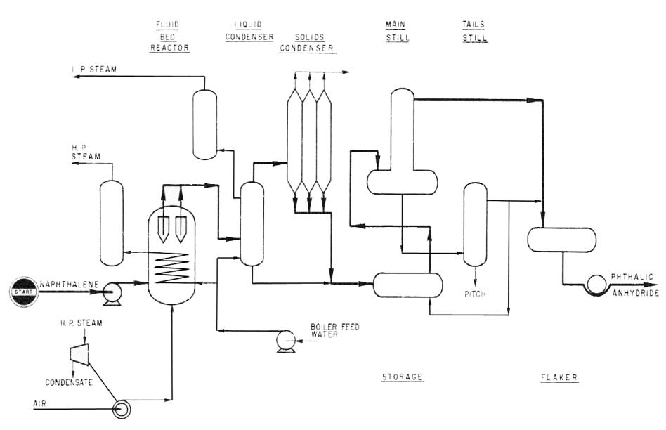
Fig. 11. Phthalic anhydride (II) production scheme
92
TEXT 10. TEREPHTHALIC ACID
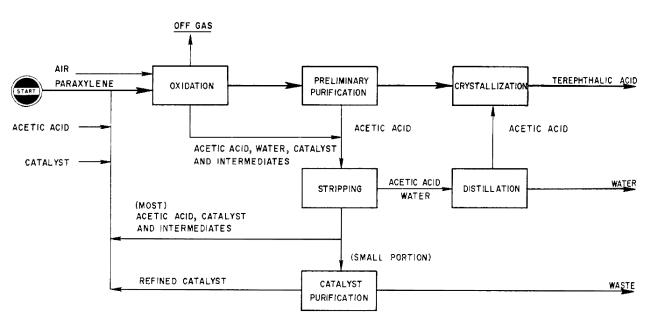
Application. A process for producing high-purity terephthalic acid (HP-TPA) by liquid phase oxidation of paraxylene with air, catalyst and acetic acid.
Description. The process consists of following three main sections. Oxidation. Paraxylene, air, catalyst and acetic acid as solvent are charged to
the liquid-phase oxidation reactor which is operated at a moderate temperature and pressure. The oxidation reaction can be carried out continuously in the presence of a considerable quantity of the cobalt compound catalyst. Crude TPA is separated from the mother liquor, which is composed of the catalyst, intermediate oxidates, water and solvent.
Purification: The crude TPA is slurried with more acetic acid and fed to a proprietary preliminary purification step. The pre-purified TPA is dissolved in acetic acid, crystallized, separated and dried to give the final, fiber-grade product.
Recovery: The mother liquors from the oxidation and purification section are fed to this section.
A portion of acetic acid and water are stripped from the mother liquor and acetic acid is purified by distillation and then recycled to the purification section.
Most of the bottom products which contains acetic acid, the catalyst and the intermediate oxidates is circulated directly to the oxidation section and only a small portion of the bottom products is subjected to an effective catalyst purification for recirculation to the oxidation process. The catalyst, solvent and intermediate oxidates are recovered at a very high yield.
Consumption of Materials. Per 100 kg of HP-TPA:
рага-xylene |
65 |
kg |
acetic acid |
10 |
kg |
catalyst |
0.1 |
kg |
Fig. 12. Terephthalic acid production scheme
93
TEXT 11. SODIUM NITRILOTRIACETATE (SNTA)
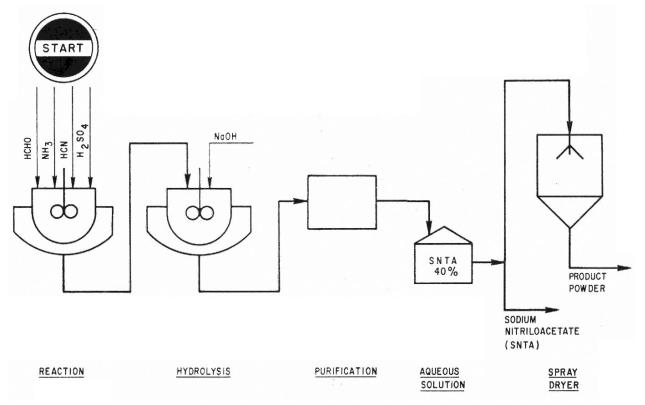
Application. A process for the manufacture of SNTA from ammonia, formaldehyde, hydrogen cyanide and caustic soda.
Description. The reaction occurs in the following two stages.
H2SO4 NH3 + 3HCHO + 3HCN – – →N(CH2СN)3 + 3H2O
N(CH2CN)3 + 3NAOH + 3H2O → N(CH2COONa)3 + 3NH3
The crude product is then purified giving a 40% aqueous solution. To obtain a powder product the solution is passed through a spray dryer. Purity is very high and product is available in the form of a liquid (40% aqueous solution) or powder.
Features:
1.Continuous process. The batch process for small scale use has been improved into a continuous process for large scale operations. The improvement has made the operation steady and reduced the number of operators.
2.High yield. This, unique process produces less byproducts than other processes. Therefore, higher yield and high purity are obtained.
3.Utilization of byproduct hydrogen cyanide. SNTA has been given less attention than EDTA in spite of its superior effect as a chelating agent because of its high cost. However, its cost can be greatly reduced by using by-produced hydrogen cyanide which is otherwise burned. Ordinarily such hydrogen cyanide is obtained in the production of acrylonitrile by the Sohio process. This should encourage the use of SNTA especially as a builder for synthetic detergents.
Fig. 13. Sodium nitrilotriacetate (SNTA) production scheme
94
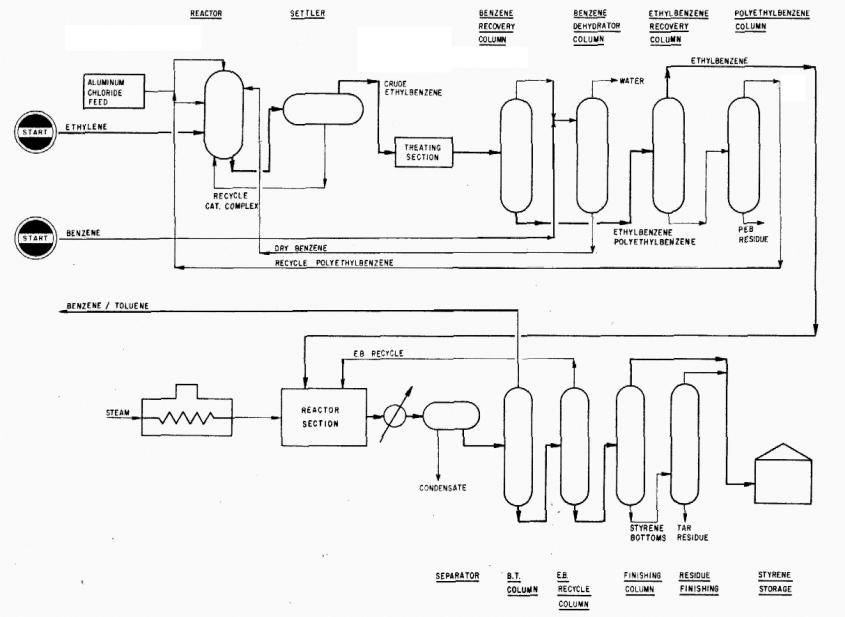
Fig.14. Styrene acid production scheme
95
TEXT 12. STYRENE
Application. Process for manufacturing styrene monomer by the alkylation of benzene and ethylene to ethyl-benzene and subsequent dehydrogenation of the ethylbenzene to styrene.
Description. Benzene is contacted with ethylene gas in the presence of aluminum chloride and recycle polyethyl-benzene. The reactor effluent is decanted in a settler, and the heavy catalyst complex layer is recycled to the reactor.
Crude ethylbenzene from the settler is treated to remove traces of chlorides and charged to the distillation system. Here, recycle benzene is first separated from the crude ethylbenzene, and the product ethylbenzene is separated from the heavy components. The heavy components are finally distilled to separate polyethylbenzene for recycle to the reactor.
Ethylbenzene purity is consistent with the manufacture of polymer grade styrene.
In the styrene section, fresh ethylbenzene is combined with recycle ethylbenzene and charged to the dehydrogenation reaction section in admixture with superheated steam. Reaction pressure and temperature are major control variables for maintaining a high conversion per pass.
The styrene monomer recovery section consists of three columns. The small amount of benzene and toluene produced by cracking in the dehydrogenation reaction is removed in the first column and returned to the ethylbenzene system. Ethylbenzene for recycle is separated from the styrene monomer in the second column. The separation is accomplished in a single high efficiency column which results in savings in investment and operating costs as compared with the conventional twocolumn system. Inhibitors are added to minimize polymer formation. The styrene monomer is separated in the third column from small amounts of tar and polymer formed during the operation.
LITERATURE USED
1.British Chemical Engineering and process technology. London. September, 1998.
2.Chemical Engineering Progress. New York. March, 1996.
3.Hydrocarbon Engineering. August, 2003.
4.Hydrocarbon Processing. May, 2001.
96