

диафрагмированные волноводные фильтры / d0b6eab4-ee66-48f9-8028-3068c251b6eb
.pdfdark as in the daytime, radar is a way of seeing things in the dark, and through clouds and fog.
1.2Radar Development
Today RADAR is a common word in vocabularies but it derived from the expression radio detection and ranging. The basic concepts of radar were developed in the late 19th and early 20th centuries. The actual development of radar is between World War I and World War II as a tool for detecting enemy aircrafts from long distances. However, it was just before and during World War II that radar emerged as a practical engineering device. Hülsmeyer, a German engineer
experimented the first detection of reflected
electromagnetic energy from a ship in 1903. But because of
the inadequate technology the range of detection was a
little more than about a mile. Detecting enemy planes and ships and of navigating across land and sea with the aid of invisible radio waves attracted the attention of military researchers. In the 1930s, several laboratories developed early versions of radar systems such as U.S. Naval Research Laboratory (NRL). In the United States, radar was born and developed at the NRL in the mid-1930s. The first detection of an aircraft is in 1930 by L. A. Hayland from NRL. The operating frequency of this radar was around 26 MHz. By the developing technology the operating frequency of the equipment used in radar systems are increased and higher frequencies used in radars. A list of radar frequencies are given in Appendix A.
Prior to World War II, NRL engineers overcame many obstacles and made great advances in developing radar. These included generating high-pulse power suitable for radar usage; creation of the duplexer, which enabled the transmitter and receiver to be used with a single antenna; development of a suitable map-like display for recognizing
2
and interpreting information provided by the radar. In the United States much of radar research also took place at the Massachusetts Institute of Technology’s (MIT) Radiation Laboratory. Engineers and scientists at Radiation Laboratory designed almost half of the radar deployed in World War II. The radar project in MIT became one of the largest wartime
projects ever, employing nearly 4000 people World War II
[2]. During the war more than 100 different radar systems were developed there. During World War II radar was used by both the English and the Germans. But it was the perfection of the technology by the England, with further design,
development |
and |
production |
support from Canada and the |
||||
United |
States, |
that |
helped |
Britain |
successfully |
defend |
|
itself |
from |
Germans. |
England |
was very |
vulnerable to |
attacks |
|
from the German air force, and so in the late 1930s a
network of radars was constructed along the southern English coast called “Chain Home”. These radars used shortwave pulses to detect incoming German aircrafts for early warning of air attacks.
By the development of radar, its application areas become larger as well. The major use of radar is in military
applications such as surveillance, navigation and control
and guidance of weapons. Since its use in World War II, radar has been used extensively by the military for a wide variety of missions, such as detection and tracking of aircraft, missiles and satellites, or other space objects. Because of its ability to detect airborne or space borne objects at great ranges (hundreds to thousands of miles), radar is an integral part of most air and missile defense systems. In addition to their current use in military operations, radars have many civilian uses as well. They are used extensively for air traffic control, geographic mapping, aircraft navigation and remote sensing. Radars are
3
generally capable of performing many tasks but are often categorized according to the main function performed by the system. Some of the common radar types are given below:
Simple Pulse Radar,
Pulse Doppler Radar,
Continuous-Wave (CW) Radar,
Frequency-Modulated Continuous-Wave (FM-CW) Radar,
Moving Target Indication (MTI) Radar,
High-Range-Resolution Radar,
Pulse-Compression Radar,
Synthetic Aperture Radar (SAR),
Inverse Synthetic Aperture Radar (ISAR),
Side-Looking Airborne Radar (SLAR),
Imaging Radar,
Interferometric SAR (IFSAR),
Tracking Radar,
Scatterometer Radar,
Track-While-Scan Radar, and
Electronically Scanned Phased-Array Radar.
In Chapter 2, some fundamental formulations used for radar analysis are given and some of the radar types including Simple Pulse Radar, Continuous Wave (CW) Radar, Frequency Modulated Continuous Wave (FMCW) Radar and Pulse Frequency Modulated CW Radar are mentioned briefly.
4
CHAPTER 2
ELECTROMAGNETIC FUNDEMENTALS OF RADAR
2.1Basic Radar Systems
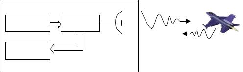
Radar operating principle is based upon the scattering properties of electromagnetic waves which reflect from various objects. In a radar system the electromagnetic wave travels in various media and scatters from any object. The incident wave scatters from the object and the receiver of the radar system detects the reflected wave from the object (target). Figure (2.1) is the simplified scheme of a monostatic radar system [3].
Transmitter |
Duplexer |
|
Antenna |
Receiver |
|
Transmitted Wave
Reflected Wave
Figure 2.1 Monostatic radar system
Monostatic radar utilizes a common antenna both for transmitting and receiving. Monostatic radars are more conventional compared to bistatic radars. A bistatic radar is one in which the transmitting and receiving antenna separated by a considerable distance. Figure (2.2) is the simplified scheme of a basic bistatic radar system.
5
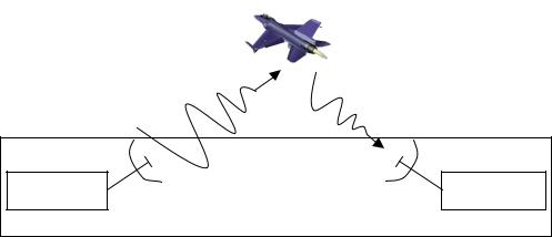
Transmitted Wave |
Reflected Wave |
Transmitter |
Transmitting |
Receiving |
Receiver |
|
Antenna |
Antenna |
|
Figure 2.2 Bistatic radar system
The radar measurements for the bistatic radars are much more complicated and difficult to accomplish when compared to conventional monostatic radars.
2.2Radar Equation
The most important aspect equation. Radar equation includes transmitted and reflected power. the radar range equation is for equation, that is:
of |
radar is |
the radar |
all |
relation |
between the |
The most general case of the bistatic radar range
|
|
Pr = |
Pt |
|
Gt |
|
|
Gr λ2 |
(2.2) |
||
|
|
|
|
|
|
|
|
|
|||
|
|
4 |
π R2 |
4 π R2 |
|
4π |
|||||
where; |
|
|
|
|
t |
|
r |
|
|
|
|
|
|
|
|
|
|
|
|
|
|
|
|
Pr |
= |
reflected power |
at the receiver antenna site, |
||||||||
Pt |
= |
transmitted |
power from the transmitter antenna, |
||||||||
Gt |
= |
gain of the |
transmitting antenna, |
|
|||||||
Gr |
= |
gain of the |
receiving antenna, |
|
|||||||
= radar cross section,
= wavelength of the signal,
Rt |
= |
distance |
from |
target |
to |
transmitting antenna, |
Rr |
= |
distance |
from |
target |
to |
receiving antenna. |
6

Equation (2.2) does not include polarization and reflection losses. We can divide the radar range equation into smaller pieces so that we can understand the whole equation. Power flux density incident on the target is
Pt |
Gt |
(2.3) |
4 π R2 |
||
|
t |
|
Gain of the antenna (G) is defined as the ratio of the intensity, in given direction, to the radiation intensity that would be obtained if the power accepted by the antenna were radiated isotropically. Another sub equation;
|
(2.4) |
|
4π Rr2
defines the isotropically scattered power density at the position of the receiving antenna. Radar cross section of the target is . The final part of the equation
Gr λ |
2 |
(2.5) |
4π |
|
|
|
|
defines the effective area of the receiving antenna.
Effective area represents the amount of the physical area of an antenna that serves as an electrical antenna.
Radar range equation constructs the fundamentals of
the radar system principles. Equation (2.1) has given for a
bistatic radar system (Figure 2.1) which the transmitting
and receiving antennas are located at different locations. For monostatic radar systems (Figure 2.2) which one antenna is used for both transmitting and receiving purposes, the radar range equation can be written as
Pr = |
|
G |
|
|
|
G λ 2 |
= |
PtG2λ 2 |
(2.6) |
|
|
|
|
|
|
|
|
|
|||
Pt 4 π R2 4 π R2 |
|
4π |
|
(4π)3R4 |
||||||
|
|
|
||||||||
7

where Rt and Rr is equal to each other and represented by R. Receiving and transmitting antennas are the same so the distance from receiving antenna to target (Rr) is equal to transmitting antenna to target (Rt). Equation (2.6) expresses the power received from a target at distance R and whose RCS is , the operating wavelength is and the gain of the antenna is G. In this simple form of radar equation losses that occurs from the radar system are not included. In actual radar systems some of these losses are very real and cannot be ignored.
2.3Radar Cross Section
In radar terminology another important property of the targets is the radar cross section, i.e. in Equation (2.4). Radar cross section ( ) or RCS of a target is defined by as the area intercepting that amount of power which, when scattered isotropically, produces at the receiver a density which is equal to that scattered by the actual target [4].
RCS |
Table 2.1 RCSs of some objects at microwave |
is |
|
|
|
||
|
frequencies |
|
|
|
|
|
|
|
Object |
Typical RCS |
|
|
|
|
|
|
Pickup Truck |
200 |
|
|
|
|
|
|
Automobile |
100 |
|
|
|
|
|
|
Large bomber or jet airliner |
40 |
|
|
|
|
|
|
Medium bomber |
20 |
|
|
|
|
|
|
Large fighter aircraft |
6 |
|
|
|
|
|
|
Small fighter aircraft |
2 |
|
|
|
|
|
|
Human being |
1 |
|
|
|
|
|
|
Conventional winged missile |
0,5 |
|
|
|
|
|
|
Bird |
0,01 |
|
|
|
|
|
8
used to determine the scattering characteristics of a
target. RCS of a target depends on the shape, size, material, properties of the target and the frequency, polarization and angle of arrival of the incident wave. The unit of RCS of a three dimensional target is square meters. Table (2.1) gives RCSs of some objects.
2.4Common Types of Radar
2.4.1Pulse Radar
Pulse radar is the common radar type used today. The transmitted waveform is a train of narrow rectangular pulses modulating a sinewave carrier. The transmitter is turned on and off to generate repetitive train of pulses. Peak power and duration of the pulses and pulse repetitions frequency (prf) changes regarding to functionality of the radar. After
a pulse is transmitted, radar listens for the echoes from
the targets until the next pulse transmitted. The distance
of the target is determined by the amount of time
transmitted signal is traveled from antenna to object of
interest |
(target) and back from object to the antenna. |
|
|||
Since electromagnetic |
energy propagates at the |
speed |
|||
of light |
c = 2.99795 x 10 8 m/s, the range R is |
|
|||
|
R |
= |
cTR |
|
(2.7) |
|
|
||||
|
|
2 |
|
|
|
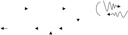
TR is the total time elapsed between the transmission of the wave and receiving the reflected wave from the target. In Equation (2.7) division by 2 comes from the two way propagation of the wave. Figure (2.3) show a simplified diagram of a pulse radar system.
9
|
|
Pulse |
|
|
|
|
|
|
|
|
|
|
|
|
|
|
|
|
|
|
|
|
Transmitter |
|
|
|
|
|
Duplexer |
|
|||||||||
|
Modulator |
|
|
|
|
|
|
|
|
|
|||||||||
|
|
|
|
|
|
|
|
|
|
||||||||||
|
|
|
|
|
|
|
|
|
|
|
|
||||||||
|
|
|
|
|
|
|
|
|
|
|
|
|
|
|
|
|
|
|
|
|
|
|
|
|
|
|
|
|
|
|
|
|
|
|
|
|
|
|
|
|
|
|
|
|
|
|
|
|
|
|
|
|
|
|
|
|
|
|
|
OUTPUT |
|
|
|
|
|
|
|
|
|
|
|
|
|
|
|
Low Noise |
|
||
|
IF Amplifier |
|
|
|
Mixer |
|
|
|
|
|
|||||||||
|
|
|
|
|
|
|
Amplifier |
|
|||||||||||
|
|
|
|
|
|
|
|
|
|||||||||||
|
|
|
|
|
|
|
|
|
|
|
|
|
|
|
|
|
|
|
|
|
|
|
|
|
|
|
|
|
|
|
|
|
|
|
|
|
|||
|
|
|
|
|
|
|
|
|
|
Local |
|
|
|
|
|
||||
|
|
|
|
|
|
|
|
|
|
Oscillator |
|
|
|
|
|||||
|
|
|
|
|
|
|
|
|
|
|
|
|
|
|
|
|
|
|
|
Figure 2.3 Pulse radar system
When the distance of the target is so long the reflected wave can be received after the second pulse transmitted so ambiguities may occur. The maximum unambiguous distance is related to pulse repetition frequency (fp) and given by equation (2.8). Higher pulse repetition interval results longer unambiguous distance. Range ambiguities can be avoided by lowering the pulse repetition frequency and this means a low sampling rate.
Equation (2.8) is applicable for monostatic pulse radars which have a common antenna used for transmitting and receiving the signal.
Runamb = |
c |
(2.8) |
|
2fp |
|||
|
|
The very first application of range determination by pulsed signals was in 1925 by Breit and Tuve for measuring
the height of ionosphere [5].
The maximum distance Rmax of the pulsed radar is directly proportional to pulse repetition interval. Increasing the pulse repetition interval will increase the
10
maximum distance of the radar system. Pulse repetition period is determined essentially by the distance of the expected targets.
|
cTp |
(2.9) |
||
Rmax |
= |
|
|
|
|
|
|||
|
2 |
|
|
|
A pulse radar that extracts |
the doppler frequency |
|||
shift for the detection of the moving targets it’s called a pulse doppler radar.
2.4.2Continuous Wave (CW) Radar
Continuous wave radars transmit a signal which oscillates with a frequency of f0. Some of the transmitted signal reflects from the existing target and reflected
signal collected by the receiving antenna. If the target is in motion relative to the radar a doppler shift in the frequency of the received signal will occur. If this is the
case the |
frequency of the received signal will be f0 ± fd. |
If the |
distance from target to radar is decreasing (a |
closing |
target) the oscillation frequency f0 will increase |
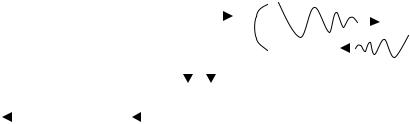
by fd, otherwise if the distance is increasing (a receding target) the oscillation frequency will decrease by fd. A simplified diagram of the continuous wave radar is given in Figure (2.4).
|
|
|
|
|
|
|
|
|
|
|
|
|
|
|
|
|
f0 |
||||
|
|
|
|
|
|
|
|
|
|
|
f0 |
||||||||||
|
|
|
|
CW |
|
|
|
||||||||||||||
|
|
|
|
|
|
|
|
|
|
|
|
|
|
|
|
|
|
|
|||
|
|
|
|
Transmitter |
|
|
|
|
|
|
|
|
|
|
|
|
|
|
|
||
|
|
|
|
|
|
|
|
|
|
|
|
|
|
|
|
|
|
||||
|
|
|
|
|
|
|
|
|
|
|
|
|
|
|
|
|
|
||||
|
|
|
|
(f0) |
|
f0 |
|
|
|
f0 ± fd |
|
|
|||||||||
|
|
|
|
|
|||||||||||||||||
|
|
|
|
|
|
|
|
|
|
|
|
|
|
|
|
|
|
|
|
f0 ± fd |
|
|
|
|
|
|
|
|
|
|
|
|
|
|
|
|
|
|
|||||
|
|
|
|
|
|
|
fd |
|
|
|
|
|
|
|
|
|
|
|
|
|
|
|
|
fd |
Beat Frequency |
|
|
|
Detector |
|
|
|
|
|
|
|
|||||||
Indicator |
|
|
|
|
|
|
|
|
|||||||||||||
|
|
Amplifier |
|
|
|
|
|
(Mixer) |
|
|
|
|
|
|
|||||||
|
|
|
|
|
|
|
|
|
|
|
|
|
|
||||||||
|
|
|
|
|
|
|
|
|
|
|
|
|
|
|
|
|
|
|
|
|
|
Figure 2.4 CW radar system
11