


3D Shapes
TUBE
TUBE n, m, mask, u1, w1, s1,
...
un, wn, sn,
x1, y1, z1, angle1,
...
xm, ym, zm, anglem
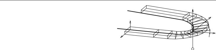
Surface generated by a polyline sweeping along a space curve path without distortion of the generating cross-section. The internal connection surfaces are rotatable in the U-W plane of the instantaneous U-V-W coordinate system.
V axis: approximates the tangent of the generator curve at the corresponding point,
W axis: perpendicular to the V axis and pointing upward with respect to the local z axis,
U axis: perpendicular to the V and W axes and forms with them a right-hand sided Cartesian coordinate system.
If the V axis is vertical, then the W direction is not correctly defined. The W axis in the previous path node is used for determining a horizontal direction.
The cross-section polygon of the tube measured at the middle of the path segments is always equal to the base polygon (u1, w1, ... un, wn). Section polygons in joints are situated in the bisector plane of the joint segments. The base polygon must be closed.
n: number of the polyline nodes. m: number of the path nodes.
ui, wi: coordinates of the base polyline nodes. si: status of the lateral edges.
xi, yi, zi: coordinates of the path curve nodes.
Note: The path comprises two points more than the number of generated sections. The first and the last points determine the position in space of the first and the last surfaces belonging to the TUBE. These points only play a role in determining the normal of the surfaces, they are not actual nodes of the path. The orientation of the surfaces is the same as that of the surfaces that would be generated at the nodes nearest to the two endpoints, if the TUBE were continued in the directions indicated by these.)
anglei: rotation angle of the cross-section.
Masking:
mask = j1 + 2*j2 + 16*j5 + 32*j6 + 64*j7 where j1, j2, j5, j6, j7 can be 0 or 1.
78 |
ArchiCAD 11 GDL Reference Guide |
|
|
3D Shapes |
j1 |
(1): base surface is present. |
|
j2 |
(2): end surface is present. |
W |
m |
||
j5 |
(16): base edges (at x2, y2, z2) are visible. |
m-1 |
V |
||
j6 |
(32): end edges (at xm-1, ym-1, zm-1) are visible. |
W |
1 |
||
j7 |
(64): cross-section edges are visible, surface is articulated. |
2 |
alpha |
||
Parameter restrictions: |
U |
|
U |
||
n > 2 and m > 3
Status values:
0:lateral edges starting from the node are all visible.
1:lateral edges starting from the node are used for showing the contour.
Additional status codes allow you to create segments and arcs in the planar polyline using special constraints.
See “Parametric Objects” in the Virtual Building chapter of the ArchiCAD 10 Help.
ArchiCAD 11 GDL Reference Guide |
79 |

3D Shapes
Examples:
TUBE 4, 18, 16+32, |
|
|||||||
|
2.0, |
|
0.0, |
0, |
||||
|
0.0, |
|
0.0, |
0, |
||||
|
0.0, |
|
0.4, |
0, |
||||
|
2.0, |
|
0.4, |
0, |
||||
|
-1, 0, 0, |
0, |
||||||
|
0, |
0, |
0, |
0, |
0, |
|||
|
4, |
0, |
0.1, |
|
||||
|
6, |
0, |
0.15, |
0, |
||||
6+4*SIN(15), |
|
4 |
- 4*COS(15), 0.2, 0, |
|||||
6+4*SIN(30), |
|
4 |
- 4*COS(30), 0.25, 0, |
|||||
6+4*SIN(45), |
|
4 |
- 4*COS(45), 0.3, 0, |
|||||
6+4*SIN(60), |
|
4 |
- 4*COS(60), 0.35, 0, |
|||||
6+4*SIN(75), |
|
4 |
- 4*COS(75), 0.4, 0, |
|||||
10, 4, |
0.45, |
|
0, |
|
- 4*COS(105), 0.5, 0, |
|||
6+4*SIN(105), |
4 |
|||||||
6+4*SIN(120), |
4 |
- 4*COS(120), 0.55, 0, |
||||||
6+4*SIN(135), |
4 |
- 4*COS(135), 0.6, 0, |
||||||
6+4*SIN(150), |
4 |
- 4*COS(150), 0.65, 0, |
||||||
6+4*SIN(165), |
4 |
- 4*cos(165), 0.7, 0, |
||||||
6, 8, |
0.75, |
0, |
|
|
||||
0, 8, |
1, |
0, |
|
|
|
|
||
-1, 8, 1, |
|
0 |
|
|
|
|
||
80 |
ArchiCAD 11 GDL Reference Guide |
3D Shapes
TUBE |
14, 6, 1+2+16+32, |
||||||
|
0, |
0,0, |
|
|
|
|
|
|
0.03, |
0,0, |
0, |
|
|||
|
0.03, |
0.02, |
|
||||
|
0.06, |
0.02, |
0, |
0, |
|||
|
0.05, |
0.0699, |
|||||
|
0.05, |
0.07, |
1, |
|
|||
|
0.05, |
0.15, |
901, |
||||
|
1, |
0, |
801, |
|
|
||
|
0.08, |
90, |
2000, |
||||
|
0.19, |
0.15, |
0, |
|
|||
|
0.19, |
0.19, |
0, |
|
|||
|
0.25, |
0.19, |
0, |
|
|||
|
0.25, |
0.25, |
0, |
|
|||
|
0, |
0.25, |
|
0, |
|
|
|
|
0, |
1, |
0, |
|
0, |
0, |
0, |
|
0, |
0.0001, |
|||||
|
0, |
0, |
0, |
|
0, |
0, |
|
|
-0.8, |
0, 0, |
|
||||
|
-0.8, |
0.0001, 0, 0, |
|||||
TUBE |
-0.8, |
1, 0, |
0 |
|
|||
3, 7, |
16+32, |
|
|||||
|
0, |
0, |
0, |
|
|
|
|
|
-0.5, |
0, 0, |
|
|
|||
|
0, |
0.5, |
0, |
|
|
||
|
0.2, 0, -0.2, 0, |
||||||
|
0, |
0, |
0, |
|
0, |
|
|
|
0, |
0, |
5, |
|
0, |
|
|
|
3, |
0, |
5, |
|
0, |
|
|
|
3, |
4, |
5, |
|
0, |
|
|
|
3, |
4, |
0, |
|
0, |
|
|
|
3, 3.8, -0.2, 0 |
||||||
ArchiCAD 11 GDL Reference Guide |
81 |