


3D Shapes
Additional parameters:
top_material, bottom_material: top and bottom materials
Example:
BEAM 1, 1, 1, 1, 1,
0.3, 0.0, 7.0, 7.0, 0.0, 0.0, 0.0, 0.1, 0.1, 0.5, 15, 15, 15, 15
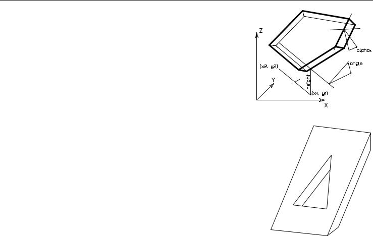
CROOF_
CROOF_ top_material, bottom_material, side_material, n, xb, yb, xe, ye, height, angle, thickness, x1, y1, alpha1, s1,
...,
xn, yn, alphan, sn
A sloped roof pitch with custom angle ridges.
top_material, bottom_material, side_material: name/index of the top, bottom and side material. n: the number of nodes in the roof polygon.
xb, yb, xe, ye: reference line (vector).
height: the height of the roof at the reference line (lower surface).
angle: the rotation angle of the roof plane around the given oriented reference line in degrees (CCW). thickness: the thickness of the roof measured perpendicularly to the plane of the roof.
ArchiCAD 11 GDL Reference Guide |
53 |
3D Shapes
xi, yi: the coordinates of the nodes of the roof ’s lower polygon.
alphai: the angle between the face belonging to the edge i of the roof and the plane perpendicular to the roof plane, -90° < alphai < 90°. Looking in the direction of the edge of the properly oriented roof polygon, the CCW rotation angle is positive.
The edges of the roof polygon are oriented properly if, in top view, the contour is sequenced CCW and the holes are sequenced CW.
si: status code that allows you to control the visibility of polygon edges and side surfaces. You can also define holes and create segments and arcs in the polyline using special constraints.
See “Status Codes” on page 139 for details.
Restriction of parameters: |
|
||
n >= 3 |
|
|
|
Examples: |
|
|
! materials |
CROOF_ 1, 1, 1, |
|||
9, |
0, |
|
|
0, |
|
! reference line (xb,yb)(xe,ye) |
|
1, 0, |
|
||
0.0, |
|
! height |
|
-30, |
|
! angle |
|
2.5, |
|
! thickness |
|
0, 0, -60, 15, |
|||
10, |
0, |
0, |
15, |
10, 20, -30, 15, |
|||
0, |
20, |
0, |
15, |
0, 0, 0, -1, |
|||
2, |
5, |
0, |
15, |
8, |
5, |
0, |
15, |
5, |
15, |
0, |
15, |
2, 5, 0, -1
54 |
ArchiCAD 11 GDL Reference Guide |

3D Shapes
L=0.25
R=(0.6^2+L^2)/(2*L)
A=ASN(0.6/R)
CROOF_ "Roof Tile", "Pine", "Pine",
16, |
2, |
0, |
0, |
|
||
0, 0, |
|
45, -0.2*SQR(2), |
||||
0, |
0, |
|
0, |
15, |
|
|
3.5, |
0, |
0, |
15, |
|||
3.5, 3, -45, |
15, |
|||||
0, |
3, |
|
0, |
15, |
|
|
0, 0, |
|
0, -1, |
|
|||
0.65, |
|
1, -45, 15, |
||||
1.85, |
|
1, |
0, |
15, |
||
1.85, |
|
2.4-L, |
0, 13, |
|||
1.25, |
|
2.4-R, |
0, 900, |
|||
0, 2*A, 0, 4015, |
||||||
0.65, |
|
1, 0, -1, |
||||
2.5, |
2, |
45, |
15, |
|||
3, |
2, |
|
0, |
15, |
15, |
|
3, 2.5, -45, |
||||||
2.5, |
2.5, |
0, |
15, |
|||
2.5, |
|
2, 0, -1 |
||||
ArchiCAD 11 GDL Reference Guide |
55 |
3D Shapes
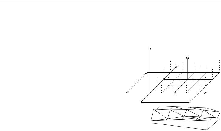
MESH
MESH a, b, m, n, mask, z11, z12, ... z1m, z21, z22, ... z2m,
...
zn1, zn2, ... znm
A simple smooth mesh based on a rectangle with an equidistant net. The sides of the base rectangle are a and b; the m and n points are along the x and y axes respectively; zij is the height of the node.
Masking:
mask = j1 + 4*j3 + 16*j5 + 32*j6 + 64*j7 where j1, j3, j5, j6, j7 can be 0 or 1.
j1 (1): base surface is present.
j3 (4): side surfaces are present.
j5 (16): base and side edges are visible.
j6 (32): top edges are visible.
j7 (64): top edges are visible, top surface is not smooth.
Parameter restrictions: m >= 2, n >= 2
Z |
|
|
|
|
|
Zij |
|
|
|
Y |
|
|
n |
|
|
|
j |
|
|
b |
|
|
|
1 |
|
|
|
1 |
i |
m |
X |
|
|
||
|
a |
|
|
Examples:
MESH 50, 30, 5, 6, 1+4+16+32+64, 2, 4, 6, 7, 8, 10, 3, 4, 5, 6, 7, 9, 5, 5, 7, 8, 10, 9, 4, 5, 6, 7, 9, 8, 2, 4, 5, 6, 8, 6
56 |
ArchiCAD 11 GDL Reference Guide |