

0.1 For Music?
The LFE channel came along with the introduction of AC-3 and Digital Theater System (DTS) to the Laser Disc and DVD media for the purpose of reproducing the channel that had been prepared for the theater at home. Naturally then, it seems logical to supply the function for audio-only media, like multichannel disc formats. While many may question the utility of the added low-frequency headroom for music, multichannel music producers are already using the channel. Among its advantages are not just the added LF headroom, but the accompanying decrease in intermodulation distortion ofthe main channel loudspeakers when handling large amounts of low bass. If the bass required to sound loud were to be put into the main channels, it would cause such intermodulation,
59
but in a separate channel, it cannot. Whether this is audible or not is certainly debatable, but it is not debatable that having a separate channel reproduced by a subwoofer eliminates the possibility of intermodulation (except in the air of the playback room at really high levels!).
What is most important to the use of LFE for music is the understanding that standards exist for the bandwidth and level of the LFE channel compared to the main channels. Since the bandwidth is controlled by the media encoders, getting the monitor level for the 0.1 channel right is the bottom line.
First, however, it is important to know that what you are monitoring has the correct bandwidth. If you record a bass drum to the LFE channel of a digital multitrack, then play it back in your studio to a subwoofer, you have made a mistake. The problem is that the only bandwidth limiting being done is the high-frequency limit of your subwoofer. You may be very surprised to find that after the tape is mastered, the bass drum has lost all of its "thwack," because the bandwidth I imitation of the LFE channel has come into play. Correct bass management in the studio will allow you to hear what the format encoder is going to do to the LFE channel, and you can mix the higher frequencies of the bass drum into the main channels, as well as its fundamentals into the LFE channel, for best reproduction.
Note that all systems employing the 5.1- or 7.1-channel configurations, whether they are on film or disc, or intended for broadcast, and whether coded by linear PCM, AC-3, DTS, or MPEG, all have two vital specifications that are the same: the sample rate of the LFE channel is 240 Hz for 48kHz sampled systems leading to practically 120 Hz bandwidth (and proportionately lower for 44.1 kHz systems), and the intended playback level is +10dB of "in-band gain" compared to the main channels (Fig. 2-10).
"In-band gain" means that the level in each 1/3-octave band in the main operating range of the subwoofer is 10 dB above the level of each of the 1/3-octave bands of one of the main channels, averaged across its main frequency range. This does not mean that the level measured with a sound level meter will measure 10dB higher, when the LFE channel is compared to a main channel. The reason for this apparent anomaly is that the bandwidth of the main channel is much wider than that of the LFE channel, which leads to the difference—there's more overall energy in a wider bandwidth signal. In an emergency, you could set the LFE level with a sound level meter. It will not read 10dB above the level of broadband pink noise for the reason explained, but instead about 4dB, when measuring with a C-weighting characteristic available even on the simple Radio Shack sound level meter. There are many possible sources of error using just a sound level meter, so this is not a recommended practice, but may have to do in a pinch,
60

Fig. 2-10 1/3-octave band spectrum analyzer display showing one main channel level in dB SPL versus frequency in Hz.The low-frequency rolloff is typical of a home system; a professional system might roll off starting about an octave lower. The high-frequency rolloff is explained in the section on equalization. Note the average mid-band 1/3-octave level is about 70dB SPL. All of these band together add up to an overall spectrum level of 83dB SPL.

Fig. 2-11 1/3-octave band spectrum analyzer display showing level in dB SPL versus frequency in Hz of a main channel spliced to a subwoofer.This is one of the jobs of bass management—to extend the low-frequency limit on each of the main channels by applying the correct signal to one or more subwoofers.
61
F ig.
2-12
1/3-octave band spectrum analyzer display showing level versus
frequency of a properly aligned LFE channel playing over the same
subwoofer as used above.The level of pink noise on the medium is the
same as for Fig.
2-11,
but the reproduction level is +10dB of in-band gain.
ig.
2-12
1/3-octave band spectrum analyzer display showing level versus
frequency of a properly aligned LFE channel playing over the same
subwoofer as used above.The level of pink noise on the medium is the
same as for Fig.
2-11,
but the reproduction level is +10dB of in-band gain.

Fig. 2-13 Block schematic diagram of 5.1-channel systems without bass management.This is typical of all motion picture theaters and most film dubbing stages and television mixing rooms. Although the main channels are "wide range," they typically roll off below 40 Hz, so the very lowest frequencies are attenuated in the main channels.This can lead to not hearing certain problems, covered in the text.
62
An anti-aliasing, low-pass filter is included in media encoders, such as those by Dolby and DTS, in the LFE channel. If you were to listen in the studio to a non-band-limited LFE source over many subwoofer models, you would hear program content out to perhaps 1-2 kHz, which would then subsequently be filtered out by the media encoder. This means you would hear greater subwoofer bandwidth from your source channels than after encoding.Thus it is important in the studio to use a low-pass filter in monitoring the LFE channel when a media encoder is not in use. Characteristics of this filter are a bandwidth of 110 Hz, and a very steep slope.
Typical specs for the filters in pro-audio might be: (1) 50 Hz 2-pole Butterworth (12dB/octave) high pass in each main channel; (2) two 50 Hz 2-pole Butterworth (12dB/octave each) low-pass filters in series in the summed subwoofer path; and (3) 110Hz steep anti-aliasing filter in the LFE feed. Summing the electrical filters and the response of the main channel speakers and subwoofer produces a fourth-order Linkwitz-Riley acoustic response. The slopes (outside the high-pass/ low-pass symbols) and frequencies (given inside the symbols) represent typical professional system use (Fig. 2-14).
Typical specs for the filters for high-quality home theater are: (1) 80 Hz 2-pole Butterworth high pass in each main channel, (2) two 80 Hz 2-pole Butterworth low-pass filters in series in the summed subwoofer path; and (3) anti-aliasing filter for the LFE channel, built into the format decoder.
The Bottom Line
• The 0.1 channel, called LFE, is provided for more headroom below 120 Hz, where the ear is less sensitive and "needs" more SPL to sound equally loud as mid-range sound.
• LFE is a monophonic channel. For stereo bass, use the five main channels.
• Bass management in monitoring can be used to reproduce both the very low-frequency content of the main channels, as well as the LFE channel, over one or more subwoofers.
• The LFE channel recorded reference level is -30dBFS for masters using -20dBFS reference on the main channels.
• When both are measured in 1/3-octave bands using pink noise at the same electrical level, the LFE channel 1/3-octave band SPL reference is 10dB above the level of one main channel; the pink noise for the LFE channel is band limited to 120Hz, and is wideband for the main channels. (See Figs. 2-11 and 2-12, comparing the in-band level in the subwoofer operating region.)Typically, LFE will measure about 4dB above the SPL of one main channel playing
63
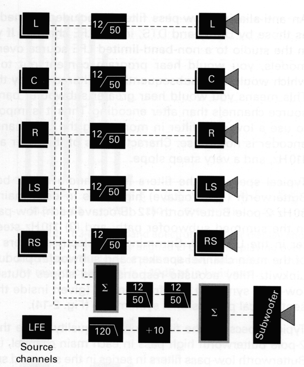
Fig. 2-14 Block diagram of a bass management system, with typical characteristics for pro-audio shown. High-pass filters in each of the main channels are complemented by a low-pass filter set in the subwoofer feed, considering the effects of the loudspeaker responses, so that each of the channels is extended downwards in frequency with a flat acoustical response. Note that this requires five matched bandwidth loudspeakers.The LFE channel is low-pass filtered with an anti-aliasing filter, which may be part of the encoding process or be simulated in monitoring, with its level summed into the bass extension of the main channels at +10dB relative to one main channel.
pink noise on a C-weighted sound level meter. The LFE level is not +10dB in overall sound pressure level compared to a main channel because its bandwidth is narrower.
Calibrating the Monitor System: Frequency Response
Equalizing monitor systems to a standard frequency response is key to making mixes that avoid defects. This is because the producer/engineer equalizes the program material to what sounds good to them (and even if not doing deliberate equalization, still chooses a microphone and position relative to the source that implies a particular frequency response), and a bass-shy monitor, for instance, will cause them to turn
64
up the bass in the mix.This is all right only if all the listeners are listening to the same monitor system; if not, then monitor errors lessen the universality of the mix. Although room equalization has a bad name among some practitioners because their experience with it has been bad, that is because there has been bad equalization done in the past.
I did an experiment comparing three different equalization methods with an unequalized monitor. I used a high-quality contemporary monitor loudspeaker in a well-qualified listening room, multiple professional listeners, multiple pieces of program material, and double-blind, level-matched experimental conditions. The result was that all three equalization methods beat the unequalized condition for all the listeners on virtually all the program material. Among the three methods of equalizing, the differences were much smaller than between equalizing and not equalizing. You will not hear this from loudspeaker manufacturers typically, but it is nonetheless true.
Considerations in choosing a set of equalizers and method of setting them are:
• The equalizer should have sufficient resources to equalize the effects of rooms acoustics; this generally means it has many bands of equalization.
• The method of equalization should employ spatial consolidation. Measuring at just one point does not well represent even human listeners with two ears. Averaging or clustering the responses and nominating one best response based at several points generally leads to less severe, and better sounding, equalization.
• Equalizers that fix just the direct field, such as those digital equalizers that operate only in the first few milliseconds, seem to be less useful in practical situations than those that fix the longer-term or steady-state response.
• If a noise-like signal is the test source for equalizing, temporal (time) averaging is necessary to produce good results. For 1/3-octave band analysis, averaging for 20 seconds generally produces small enough deviations. Trying to average the bouncing digits of a real-time analyzer by eye produces large errors.
A Choice of Standardized Response
Film sound uses the standards ISO 2969 and SMPTE 202 for the target frequency response of the monitor system. Called the X curve for extended, wide-range response, this is a nationally and internationally recognized standard that has helped interchangeability of film program material throughout the world.The US standard includes the method of measurement along with the curve (Fig. 2-15).
6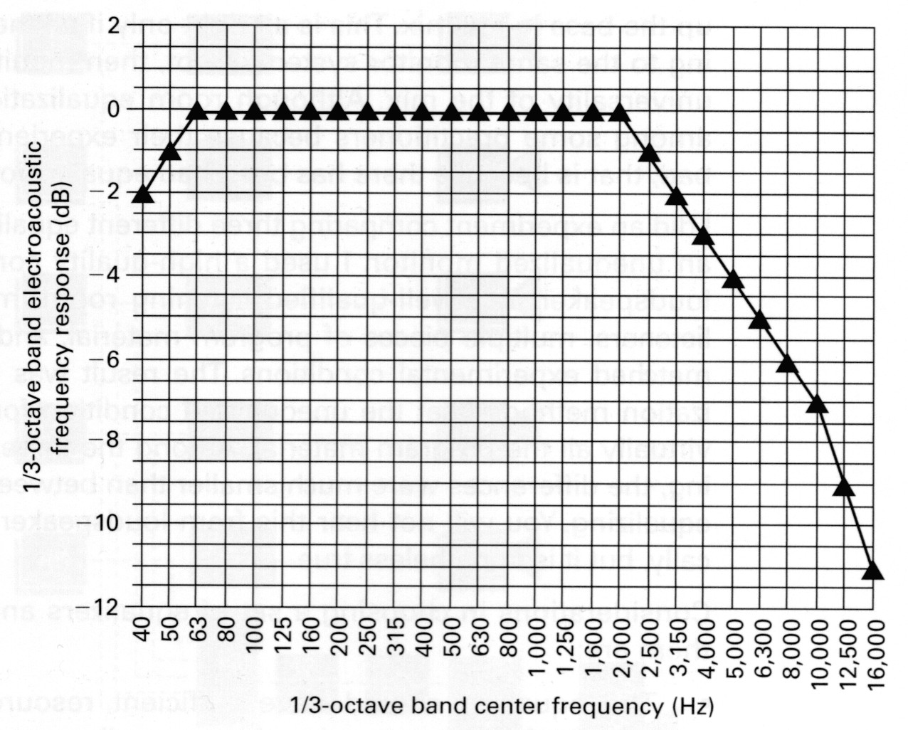 5
5
Fig. 2-15 The X curve of motion picture monitoring, to be measured spatially averaged in the listening area of the sound system with quasi-steady-state pink noise and low-diffraction (small) measurement microphones.The room volume must be at least 6,000 ft3.The curve is additionally adjusted for various room volumes; see SMPTE 202.
Television and music have no such well-established standard.They tend to use a monitor loudspeaker that measures flat anechoically on axis, thus making the direct sound flat at the listener (so long as the loudspeaker is aimed at the listener, and neglecting air loss that is extremely small in conventional control rooms). Depending on the method of measurement, this may or may not appear flat when measured at the listening location, which also has the effects of discrete reflections and reverberation.
A complication in measuring loudspeakers in rooms is that the loudspeaker directivity changes with frequency, and so does the reverberation time. Generally, loudspeakers become more directional at high frequencies, and reverberation time falls.The combination of these two means that you may be listening in the reverberant-field dominated area at low and middle frequencies, but in the direct sound dominated area at high frequencies. Thus at high frequencies the direct sound is more important than the steady state. Measured with pink noise stimulus, correctly calibrated microphones, and spatial and time averaged spectrum analysis, the frequency response will not measure flat when
66
it is actually correct. What is commonly found in control rooms is that the response is flat to between 6.3 and 12.5kHz with a typical break frequency from flat of 10kHz, and then rolls off at 6dB/octave. Basically, if I know that a monitor loudspeaker is indeed flat in the first arrival sound (and I can measure this with a different measurement method), I do not boost high frequencies during equalization. In fact, most of the equalization that is done is between 50 and 400 Hz, where the effects of standing waves dominate in rooms.
For monitoring sound from film, there needs to be a translation between the X curve and normal control room monitoring, or the film program material will appear to be too bright. This is called re-equalization, and is a part of HomeTHX.When playing films in a studio using a nominally flat monitor response such as described above, addition of a high-frequency shelf of -4dB at 10 kHz will make the sound better.
Calibrating the Monitor System: Level
Once the monitor system has been equalized, the gain must be set correctly for each channel in turn, and in a bass managed system the subwoofer level set to be correct to splice to the main channels and extend them downwards in frequency, with neither too little nor too much bass. If the bass management circuitry is correct, the in-band gain of LFE will then be the required +10dB (Fig. 2.16).
There is a difference in level calibration of motion picture theaters and their corresponding dubbing stages on the one hand, and control rooms and home theaters on the other. In film work, each of the two surround channels is calibrated at 3dB less than one of the screen channels; this is so the acoustical sum of the two surround channels adds up to equal one screen channel. In conventional control rooms and home theaters the calibration on each of the 5 channels is for equal level. An adjustment of the surround levels down by 3dB is necessary in film transfers to home theater media, and at least one media encoder includes this level adjustment in its menus.
Proper level setting relies on setting the correct relationship between studio bus level and sound pressure level at the listening location. In any one studio, the following may be involved:
• a calibrated monitor level control setting on the console;
• any console monitor output level trims;
• room equalizer input and/or output gain controls;
• power amplifier gain controls;
• loudspeaker sensitivity; or
• in the case of powered loudspeakers, their own level controls.
67

Fig. 2-16 Typical control room electroacoustic frequency response measured with quasi-steady-state pink noise spatially averaged around the listening location. The break frequency from flat varies depending on room volume, reverberation time versus frequency, speaker directivity, and size and calibration method of the measurement microphone(s). A measurement of the direct sound only with a flat measurement microphone will yield a flat response when the quasi-steady-state noise measures on a curve such as this.
You must find a combination of these controls that provides adequate headroom to handle all of the signals on the medium, and maintains a large signal-to-noise ratio.The test tape available from, Martinsound4 is an aid to adjusting and testing the dynamic range of your monitor system.The resulting work is called "gain staging," which consists of optimizing the headroom versus noise of each piece of equipment in the chain. High-level "boinks" are provided on the test tape that check headroom for each channel across frequency. By systematic use of these test signals, problems in gain staging may be overcome. As part of gain staging, one level control per loudspeaker must be adjusted for reference level setting. Some typical monitor level settings are given inTable 2-4.
The best test signal for setting level electrically is a sine wave, because a sine wave causes steady, unequivocal readings. In acoustical work, however, a sine wave does not work well. Try listening to a 1 kHz sine wave tone while moving your head around. In most environments
4http://www.martinsound.com/pd_mch.htm
68
Table 2-4 Reference Levels for Monitoring
Type of program |
SPL* for -20dBFSave |
Film |
85 |
Video |
78 |
Music |
78-93 |
*Sound pressure level in dB re 20μN/m2. SMPTE RP 200-2002 specifies an average responding, rms calibrated detector with pink noise at -20 dBFS. The sound level meter is to be used with C-weighting and the "slow" (1 s) detector time constant. |
|
you will find great level changes with head movements, because the standing waves affect a single frequency tone dramatically. Thus, noise signals are usually used for level setting acoustically, because they contain many frequencies simultaneously. Pink noise is noise that has been equalized to have equal energy in each octave of the audio spectrum, and sounds neutral to listeners; therefore, it is the usual source used for level setting.
A problem creeps in with the use of noise signals; however, they show a strong and time-varying difference between their rms level (more or less the average) and peak level. The difference can be more than 10dB. So which level is right? The answer depends on what you are doing. For level setting, we use the average or rms level of the noise, both in the electrical and in the acoustical domains. Peak meters, therefore, are not useful for this type of level setting, as they will read (variably) about 10dB too high. The best we can do is to use a sine wave of the correct average level to set the console and recorder meters, then use the same level of noise, and set the monitor channel gain, 1 channel at a time, so that the measured SPL at the listening location reads the standard inTable 2-4.
An improvement on wideband pink noise is to use filtered pink noise with a two-octave bandwidth from 500 Hz to 2 kHz. This noise avoids problems at low frequencies due to standing waves, and at high frequencies due to the calibration and aiming of the measurement microphone. Test materials using sine wave tones to calibrate meters, and noise at the same rms level to calibrate monitors, are available from the author's web site, www.tmhlabs.com.
On these test materials a reference sine wave tone is recorded at -20dBFSrms to set the console output level on the meters, and filtered pink noise over the band from 500 Hz to 2kHz is recorded at a level of -20dBFSrms to set the acoustical level of the monitor with a sound level meter. Once electrical level is set by use of the sine wave tone and console meters, the meters may be safely ignored, as
69
they may read from 1 dB low (trueVU meters, and so-called loudness meters that use an average responding detector instead of an rms one) to more than 10dB high (various kinds of peak meters). It is customary to turn up the console fader by the 1 dB to make the average level of the noise read OVU, but be careful that what you are looking at is actually a VU meter to the IEEE standard. It should read about 1 dB low average on the noise compared to the tone.
For theatrical feature work this level of noise is adjusted to 85dB on a sound level meter set to C-weighting and slow reading located at the primary listening position. For television use on entertainment programming mixed in Hollywood, reference level ranges from about 78 to 83dB SPL For music use, there is no standard, but typical users range from 78 up to 93dB.TMH 10.2-channel systems are calibrated to 85dB SPL for -20dBFSrms.
For each channel in turn, adjust the power amplifier gain controls (or monitor equalization level controls) for the reference sound pressure level at the listening location. A Radio Shack sound level meter is the standard of the film industry and is a simple and cheap method to do this. The less expensive analog Radio Shack meter is preferred to the digital one because it can be read to less than 1 dB resolution, whereas the digital meter only shows 1 dB increments.
70